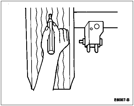
Using white chalk or paint, mark a small area at the center of each rear tire and scribe a vertical line on it.
Section 05-00: Axle and Driveshaft, Service | 1996 F-150, F-250, F-350 4x2 and 4x4, F-Super Duty and Bronco Workshop Manual |
Certain rear axle (4001) and driveline trouble symptoms are also common to the engine (6007), transmission (7003), rear wheel bearings (1225), tires and other parts of the vehicle. For this reason, make sure the cause of the trouble is in the rear axle before adjusting, repairing or replacing any of its parts. Refer to Diagnosis and Testing in Section 00-04.
Certain trouble symptoms may be caused by limited slip differentials. Check the vehicle certification and axle ratio tag to determine the type of differential.
U-Joint Inspection
Prior to checking driveline angularity, inspect the universal joints for proper operation.
Place the vehicle on a frame hoist and rotate the driveshaft (4602) by hand. Check for rough operation or seized universal joints. If the universal joint shows signs of seizure, excessive wear or improper seating, scribe alignment marks on the driveshaft and rear axle companion flange. Remove the driveshaft and remove and replace the universal joint. Install the driveshaft in the marked original position.
Alignment Inspection, Rear Axle and Suspension
Raise the vehicle on a hoist to allow the rear axle to be suspended freely.
Using white chalk or paint, mark a small area at the center of each rear tire and scribe a vertical line on it.

Adjust both wheels so that the markings face the front of the vehicle. Using a tape measure, measure the distance between scribe marks and record this reading (front reading).
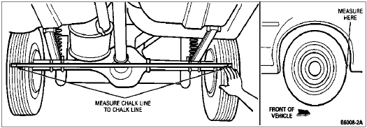
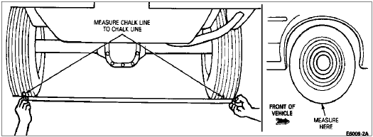
Rotate the rear wheels so the markings are directly underneath the vehicle. Measure the distance between the scribe marks and record this reading (bottom reading).
Rotate the rear wheels so the markings face the rear of the vehicle. Again, measure and record the distance between scribe marks (rear reading).
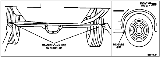
The difference between the front and rear readings obtained in Steps 3 and 5 is the toe-out or toe-in condition of the axle housing.
Toe-in occurs when the front reading is less than the rear reading. Toe-out occurs when the front reading is greater than the rear reading.
All numbers below are for example only.
Front reading: 52-3/16 inch
Rear reading: 52-1/16 inch
Toe-out: 2/16 inch (1/8 inch)
To determine camber, find the average of the front and rear readings obtained in Steps 3 and 5. Then, subtract the bottom reading (obtained in Step 4) from this.
Positive (+) camber is when the bottom reading is less than the average of the front and rear readings. Negative (-) camber is when the bottom reading is greater than the average of the front and rear readings.
Average of front and rear readings (example):
52-2/16 inch
Bottom reading: 52-2/16 inch
Difference or camber: 0
If the rear axle exceeds these guidelines, verify rear springs and suspension components are okay. If suspension is okay, remove axle and measure rear axle housing with an inclinometer to determine if axle is bent. Replace rear axle housing only if confirmed as bent.
Noise Acceptability
A gear-driven unit, especially an automotive drive axle, will produce a certain amount of noise. Some noise is acceptable and may be audible at certain speeds or under various driving conditions, such as a newly paved blacktop road. The slight noise is not detrimental to operation of the rear axle and must be considered normal.
With the Traction-Lok® Limited Slip differential axle, a slight chatter noise on slow turns after extended highway driving is considered acceptable and has no detrimental effect on the locking axle function.
Preliminary Diagnosis
Question the Customer
The preliminary diagnosis begins with the service technician asking the customer diagnostic questions; especially for conditions of noisy operation and/or vibration.
Always ask the customer about the following:
The exact nature of the symptom. If it is a vibration, how is it felt? If a noise, what kind? Is it high-pitched, a rumbling noise or some other concern?
The driving conditions in which the symptoms appear: road speed, drive or coast, on turns or on a grade only.
Whether the condition is constant or variable. Does a noise increase in pitch with speed or some other factor?
All information should be written on the service order so the technician will know where to start looking. The technician must be able to identify the axle concern from what is written on the order following the road test.
It is, of course, preferable to have the customer demonstrate the symptoms in a road test whenever possible.
Road Test
A road test is mandatory for any customer concern of noise and/or vibration that is not eliminated by the on-hoist check of chassis components. The Road Test Form is arranged to record the conditions that may be heard or felt during this test.
The Road Test Form lists four operating conditions or modes in which some axle noises come and go: drive, cruise, coast and float.
| Mode | Conditions |
|---|---|
| DRIVE | Accelerating the vehicle; a definite throttle depression applying engine torque. |
| CRUISE | Maintaining a constant speed with the throttle applied. |
| COAST | Decelerating with the throttle closed. |
| FLOAT | Controlled deceleration; backing the throttle continually to prevent either braking or accelerating torque from the engine. |
To perform a good diagnostic check, it is important to operate the vehicle in all four modes and check off those in which the noise occurs. The modes are defined in the preceding chart. Write down the kilometers per hour (miles per hour) range at which both noise and vibration occur. On vehicles equipped with overdrive transmissions, evaluate rear axle noise with the transmission in direct drive and not in overdrive. Transmission noise can be mistaken for rear axle noise when in overdrive.
Axle Diagnosis Check Sheet

Analysis of Leakage
Most rear axle leakage conditions can be corrected without a teardown. However, it is important to clean up the leaking area enough to identify the exact source.
A plugged rear axle housing vent (4022) can cause wheel or pinion seal leaks due to internal pressure buildup.
Make sure axle lubricant level is 6.4-14.2mm (1/4-9/16 inch) for Ford axles or 6.4-19.1mm (1/4-3/4 inch) for Dana axles below bottom of fill hole.
Flange Yoke Seal
When the rear axle drive pinion seal (4676) leaks, it is usually because it was not installed carefully or properly, or because of poor quality on the seal journal surface.
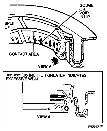
Any damage to the seal bore (dings, dents, gouges or other imperfections) will distort the seal casing and allow leakage past the outer edge of the rear axle drive pinion seal.
The rear axle drive pinion seal can be torn, cut or gouged if it is not assembled carefully. The spring that holds the rear axle drive pinion seal against the rear axle universal joint flange (4851) may be knocked out, allowing leakage past the lip.
The rubber lip can harden (like plastic) with cracks at the oil lip contact point, especially in presence of high temperatures. The contact point on the rear axle universal joint flange is usually black, indicating excessive heat. Marks, nicks, gouges or rough surface texture on the seal journal of the rear axle universal joint flange will also cause leaks. Excessive rear axle drive pinion seal wear will be noted. The rear axle universal joint flange should be replaced if any of these conditions exist.
Metal chips or sand trapped at the sealing lip also may cause oil leaks. This can cause a wear groove on the rear axle universal joint flange and heavy pinion seal wear.
When any seal leaks, confirm that air passes freely through vent hose and fitting. Clean out as needed.
Drive Pinion Nut
There have been instances of oil leaking past the threads of the pinion nut. The condition can be corrected by removing the nut and applying Pipe Sealant With Teflon® D8AZ-19554-A or equivalent meeting Ford specification WSK-M2G350-A2 on the threads and nut face.
NOTE: Be sure to follow the correct procedure for setting the bearing preload when the nut is installed.
Axle Shaft (Wheel) Seals
Axle shaft oil seals are susceptible to the same kinds of damage as rear axle drive pinion seals if improperly installed. The seal bore must be clean and the lip handled carefully to avoid cutting or tearing it. Axle shaft journal surface must be free of nicks, gouges and rough surface texture.
Casting Porosity (Holes in Casting)
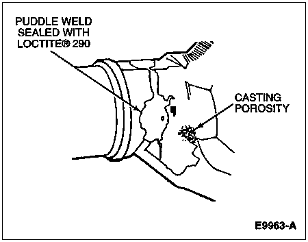
Occasionally there will be a rear axle housing (4010) leak through small holes in the cast axle housing. These holes (casting leakage) are caused by gas bubbles in the casting process and are known technically as a porous condition or porosity.
There are two recommended types of service:
Peen in a small amount of body lead. Seal the hole with Loctite® 290 or equivalent meeting Ford specification M3D35-A(E).
In larger holes (or pockets), drill a shallow hole and tap it for a small setscrew. Install the setscrew and seal it over with Locktite® 290 or equivalent meeting Ford specification M3D35-A(E).
Weld Leaks
Most minor weld leaks can be corrected with Locktite® 290 or equivalent meeting Ford specification M3D35-A(E). This includes the "puddle" or fill welds that join the axle tube to the center casting on integral axles. They sometimes leak and can be sealed easily. If a weld is broken, the rear axle housing must be replaced. The alignment is too critical for field service.
Analysis of Vibration
Few vibration conditions are caused by the rear axle. On a vibration concern, follow the diagnosis procedure in Section 00-04 unless there is a good reason to suspect the axle.
Most vibration in the rear end is caused by tires or driveline angle.
Traction-Lok® Differential
![]() WARNING: A VEHICLE EQUIPPED WITH A TRACTION-LOK® DIFFERENTIAL WILL ALWAYS HAVE BOTH WHEELS DRIVING. IF, WHILE THE VEHICLE IS BEING SERVICED, ONLY ONE WHEEL IS RAISED OFF THE FLOOR AND THE REAR AXLE IS DRIVEN BY THE ENGINE, THE WHEEL ON THE FLOOR COULD DRIVE THE VEHICLE OFF THE STAND OR JACK. BE SURE BOTH REAR WHEELS ARE OFF THE FLOOR.
WARNING: A VEHICLE EQUIPPED WITH A TRACTION-LOK® DIFFERENTIAL WILL ALWAYS HAVE BOTH WHEELS DRIVING. IF, WHILE THE VEHICLE IS BEING SERVICED, ONLY ONE WHEEL IS RAISED OFF THE FLOOR AND THE REAR AXLE IS DRIVEN BY THE ENGINE, THE WHEEL ON THE FLOOR COULD DRIVE THE VEHICLE OFF THE STAND OR JACK. BE SURE BOTH REAR WHEELS ARE OFF THE FLOOR.
Tires
![]() WARNING: DO NOT BALANCE THE REAR WHEELS AND TIRES WHILE THEY ARE MOUNTED ON THE VEHICLE. POSSIBLE TIRE DISINTEGRATION AND/OR DIFFERENTIAL FAILURE COULD RESULT, CAUSING PERSONAL INJURY AND/OR EXTENSIVE COMPONENT DAMAGE. USE OFF-VEHICLE WHEEL AND TIRE BALANCER ONLY.
WARNING: DO NOT BALANCE THE REAR WHEELS AND TIRES WHILE THEY ARE MOUNTED ON THE VEHICLE. POSSIBLE TIRE DISINTEGRATION AND/OR DIFFERENTIAL FAILURE COULD RESULT, CAUSING PERSONAL INJURY AND/OR EXTENSIVE COMPONENT DAMAGE. USE OFF-VEHICLE WHEEL AND TIRE BALANCER ONLY.
Vibration is a definite concern with modern, high-mileage tires if they are not "true" both radially and laterally. They are more susceptible to vibration around the limits of radial and lateral runout of the tire and wheel assembly. They also require more accurate balancing. Wheel and tire runout checks, truing and balancing are normally done before axle inspection.
Sometimes a vibration concern can be corrected by properly rotating or inflating the tires.
Driveline Angle
| Description | Tool Number |
|---|---|
| Pinion Angle Level Gauge | T68P-4602-A |
An incorrect driveline (pinion) angle can often be detected by the driving condition when vibration occurs.
NOTE: Driveline angles are given in relation to a 0-degree longitudinal (fore-aft) unibody frame rail angle and are specified for individual components. Refer to the Specifications portion of this section for the specified engine, driveshaft and pinion angle.
Raise the vehicle on a drive-on type hoist or back onto a front-end alignment rack. Bounce the vehicle to normalize the suspension. This ensures that the suspension components are in the normal-load condition.
Measure the ride height. The vehicle must be in the curb height (empty) condition. Find the recorded ride height in the Rear Driveline Angles charts in the Specifications portion of this section. The specified driveline angles correspond to the measured ride height.
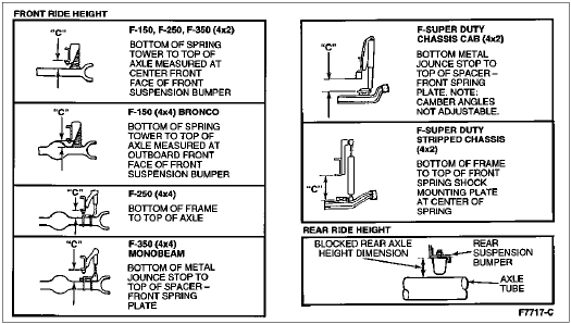
Driveline angles are measured with Pinion Angle Level Gauge T68P-4602-A or with an adjustable bubble (spirit level) protractor. The protractor is used when the tool kit is not available or when the angles to be measured are more than 12 degrees. All angles should be read within 1/2 degree with the tool or protractor held plumb on a clean, flat surface.
Place the vee magnet of Pinion Angle Level Gauge T68P-4602-A on the bottom of the vehicle frame as shown and calibrate the tool to a zero bubble reading. This gives the 0-degree frame angle. Average the readings from both sides to obtain a more accurate reading.
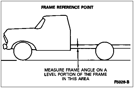
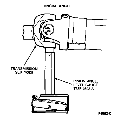
Check the engine angle by rotating the driveshaft until one transmission slip-yoke ear is parallel to the floor. Remove the retaining snap ring, if equipped, from the yoke. Install the pinion angle level gauge and record the angle reading. If the angle reading differs from the specified angle by 1 degree or more, proceed to Engine Angle Adjustments under Driveline Angle Correction in the Adjustments portion of this section and neutralize the engine and transmission mounts. With the engine angle at specifications, check the driveshaft and pinion angles. Reinstall the snap ring.
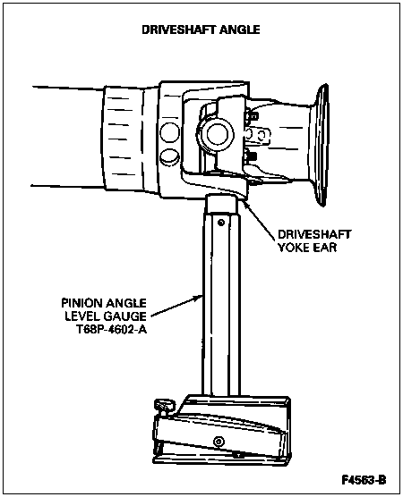
To check the driveshaft angle, rotate the driveshaft so one driveshaft yoke ear is parallel to the floor. Remove the retaining snap ring, if so equipped, from the yoke. Install the magnetic pinion angle level gauge on the U-Joint bearing cup and record the angle reading. Reinstall the snap ring. Check the pinion angle and if either or both readings are not to specification, refer to Driveshaft and Pinion Angle Adjustment in the Adjustments portion of this section.
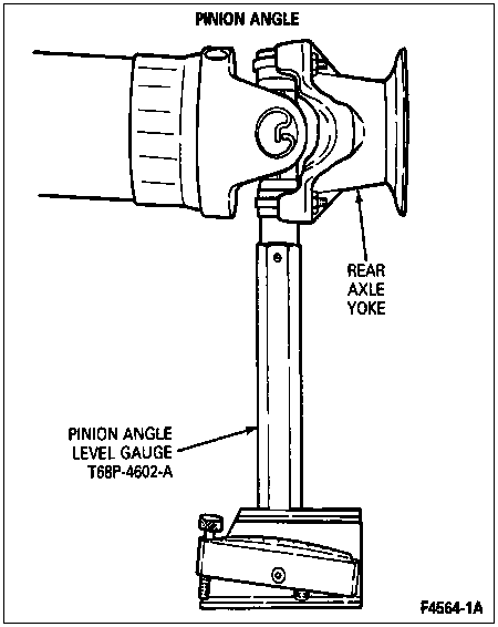
To check the pinion angle, rotate the driveshaft so that one ear of the rear axle yoke is parallel to the floor. Install the Pinion Angle Level Gauge and record the reading. If the reading is not to specifications, refer to Driveshaft and Pinion Angle Adjustment in the Adjustments portion of this section.
NOTE: When using a bubble (spirit level) protractor, the angles are read from the 0-degree frame angle. The 90-degree mark on the protractor is read as the 0-degree frame angle. For example, when the protractor is placed vertically on the component and the protractor reads 85 degrees, the component angle is actually +/-5 degrees.
To check driveline angle with adjustable bubble (spirit level) protractor, follow Steps 1 and 2 to normalize suspension and measure ride height. Place the protractor on the bottom of the vehicle frame directly below the front driver/passenger seat. This gives the 0-degree frame angle. Take and average the readings from both sides to obtain a more accurate reading.

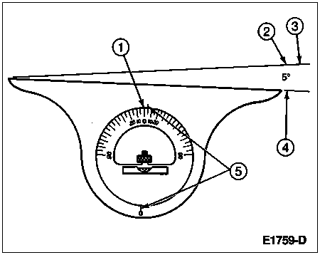
| Item | Part Number | Description |
|---|---|---|
| 1 | — | Protractor 0-Degree Mark |
| 2 | — | A 5-Degree Angle Is Read from the 0-Degree Mark |
| 3 | 5005 | Frame |
| 4 | — | Component Angle |
| 5 | — | Protractor Indexing Marks |
NOTE: If slip-yoke ears are not machined, rest protractor against bottom of starter motor (11001).
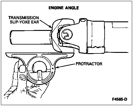
To check the engine angle, rotate the driveshaft until one transmission slip-yoke ear is parallel to the floor. Place the protractor so it is flush against the slip-yoke ear.
Make sure the protractor is not resting against any portion of the driveshaft. Record the angle reading. If the engine angle reading differs from the specified angle by 1 degree or more, proceed to Engine Angle Adjustments under Driveline Angle Correction in the Adjustments portion of this section and normalize the engine and transmission mounts. With the engine angle at specifications, check the driveshaft and pinion angles. Refer to Specifications in this section.
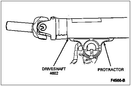
To check the driveshaft angle, place the protractor on any portion of the driveshaft tube so the plane surface of the protractor is flush against the bottom surface of the tube and parallel to the floor.
Record the reading. Subtract frame angle to get driveshaft angle. Check the pinion angle and if both or either reading is not to specifications, refer to Driveshaft and Pinion Angle Adjustment in the Adjustments portion of this section.
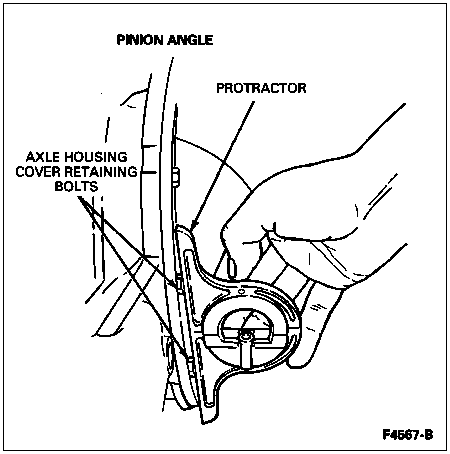
To check the pinion angle, place the protractor in a vertical position so it is flush against two axle housing cover retaining bolts. Rotate the protractor bubble indicator so the 90-degree marks align with the indexing marks. Read the protractor and calculate angle. For example, if the protractor indicates a reading of 85 degrees, the pinion angle reading is +/-5 degrees. Record the reading. If the reading is not to specification, refer to Driveshaft and Pinion Angle Adjustment in the Adjustments portion of this section.
Road test to verify resolution of condition. If driveline angle correction and driveline runout/balance procedures do not eliminate the vibration condition, the differential ring gear and pinion (4209) should be checked for backlash variation. Refer to Driveshaft Runout and Balancing in the Adjustments portion of this section.
Remove the axle housing cover (4033). Refer to Section 05-02A or Section 05-02D. Measure ring gear backlash on 30 consecutive ring gear teeth using Dial Indicator with Bracketry TOOL-4201-C or equivalent and note the variation between the high and low readings. If over 0.10mm (0.004 inch), replace the differential ring gear and pinion. Refer to Section 05-02A or Section 05-02D.

U-Joint Wear
Prior to checking driveline angularity, inspect the universal joints on the driveshaft for proper operation.
Place the vehicle on a frame hoist and rotate the driveshaft by hand. Check for rough operation or seized U-joints. If the U-joint shows signs of seizure, excessive wear or improper seating, scribe alignment marks on the driveshaft and rear axle companion flange. Remove the driveshaft and remove and replace the U-joint. Install the driveshaft in the marked original position.
U-Joint Phasing
When assembling a slip between center driveshaft, the universal joint yokes must be assembled to the driveshaft on the same plane. If not, the assembly may be out of balance, causing a driveline vibration.
NOTE: Two-piece driveshafts cannot be assembled out of phase due to a master or blind spline located on the yoke (except F-Super Duty Motorhome).
Axle Shaft Runout
Runout of the axle shaft (4234) at either end is a possible cause of rear end vibration. It is advisable to check the axle shaft for runout of the bolt circle (radial).
For bolt circle runout, refer to Section 04-04.
NOTE: If the axle shaft assembly is removed, check runout of the shaft itself. The forged (unmachined) part of the shaft is allowed to have as much as 3.0mm (0.120 inch) runout. This alone will not cause a vibration condition.
Drive Pinion Stem and Rear Universal Joint Flange
Rear axle universal joint flange runout should be checked when all other checks have failed to show the cause of vibration.
Improper installation of the rear axle drive pinion seal can cause excessive rear axle universal joint flange runout. If the spring on the seal lip is dislodged, it will jam up and cock the flange. Check that possibility before replacing the differential ring gear and pinion because of excessive rear axle universal joint flange runout.
Two-Piece Driveshaft
The two-piece driveshaft used in longer wheelbase light truck models introduces some special considerations to diagnosis and testing. As compared with a one-piece installation, the two-piece design includes a front or coupling shaft, a rubber-insulated frame-mounted driveshaft center bearing bracket, a splined slip joint and an intermediate universal joint at the front of the rear driveshaft.
Bearing Shimming
Drive-away shudder is the predominant symptom associated with driveline angles condition on vehicles with two-piece driveshafts. After eliminating coupling shaft phasing as the possible cause, driveline angles should be measured and corrected. Drive-away shudder can usually be serviced by shimming down the driveshaft center bearing bracket in 6.35mm (1/4-inch) increments using shims E0TZ-4A209-A or equivalent until the drive-away shudder is eliminated. Plate stock must be used to maintain proper preload compression of the rubber insulator.
Replace the existing bolts with the appropriate length 7/16-14 hex-head bolts.
Tighten bolts to 51-73 Nm (38-54 lb-ft).
Road test to verify resolution of condition.
If the drive-away shudder cannot be serviced by shimming down the driveshaft center bearing bracket, check driveline angle. Refer to Driveline Angle under Analysis of Vibration in the Diagnosis and Testing portion of this section.
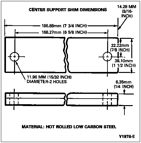
Coupling Shaft/Center Bearing Alignment
Vehicle noise and vibration can be caused by dislocated and/or failed driveshaft center bearing support rubber insulator, contaminated driveshaft center bearing support (4800) or excessive compression of the rubber insulator.
The service for this condition is as follows:
Remove the coupling shaft from the vehicle.
Remove the driveshaft center bearing bracket and retainer.
Remove the rubber insulator.
Press driveshaft center bearing support and bearing retainer off the coupling shaft.
Press the dust slinger off the coupling shaft.
Replace with Center Bearing Assembly Kit D9TZ-4800-A or equivalent in all cases except E4TZ-4800-A for F-250 HD, F-350 and F-Super Duty Chassis Cab with the ZF transmission.
Install driveshaft center bearing support in rubber insulator and press bearing on shaft with the turned-in lip toward the dust slinger (forward). The support bracket must be installed with the deep flange rearward.
Reassemble the coupling shaft.
Reinstall the driveline in the vehicle with the yokes phased properly.
Road test to verify resolution of condition.
If vibration still exists, insert 1.59mm (1/16-inch) shims between driveshaft center bearing bracket and support plate (on bolt ends of driveshaft center bearing bracket) to reduce compression of the rubber insulator as required.
Axle Noise
Refer to Symptom Chart in this section.
Non-Axle Noise
There are a few other conditions that can sound like axle noise and have to be considered in diagnosis.
The three most common are exhaust, tires and trim mouldings. Make sure that none of the following are the cause of the noise before proceeding with an axle teardown and diagnosis.
Analysis of Gear Noise
Gear Howl and Whine
Before disassembling the axle to diagnose and correct gear noise, eliminate the tires, exhaust, trim items, roof racks, axle shafts and rear wheel bearings as possible causes.
The noises listed on the Road Test Form in this section usually have specific causes that can be diagnosed by observation as the unit is disassembled. The initial clues are, of course, the type of noise heard on the road test and the driving conditions.
Bearing malfunctions will normally be obvious at disassembly. As noted earlier, inner and outer pinion bearings make a high-pitched, whistling noise, usually at all speeds. If there is only one pinion bearing that is malfunctioning, the noise may vary in different driving phases.
Pinion bearings are frequently replaced unnecessarily on axles with low mileage under 24,139 km (15,000 miles) when correcting gear noise. They should not be replaced unless they are actually scored or damaged, or there is a specific differential pinion bearing noise. Examine the large end of the rollers for wear. If the pinion bearing's original blend radius has worn to a sharp edge, the pinion bearing should be replaced.
Remember that the low-pitched rumble of a malfunctioning wheel bearing can also be caused by the exterior luggage rack or tires.
Rear wheel bearing noise might be mistaken for pinion bearing noise. Inspect the rear wheel bearing carefully before tearing down the axle.
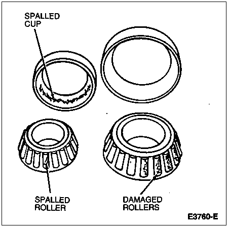
For 8.8-inch or 10.25-inch (semi-floating) axles, the rear wheel bearings are pressed into the axle housing tubes, making them more difficult to check. However, the axle shaft is the inner race for the bearing. If the bearing is damaged, the roller surface on the axle shaft may also be damaged. The rollers run approximately on the center of the polished surface.

Chuckle
Chuckle that occurs on the coast driving phase is usually caused by excessive clearance between the differential gear hub and the differential case bore. It can also be caused by a damaged tooth on the coast side of the pinion or ring gear.
Any damage to a gear tooth on the coast side can cause a noise identical to chuckle. Even a very small tooth nick or ridge on the edge of a tooth is enough to cause the noise.
You can often correct this condition and eliminate the noise simply by cleaning up the gear tooth nick or ridge with a small grinding wheel. If the cleaned up or damaged area is larger than 3.2mm (1/8 inch), it is advisable to replace the gearset.
To check the differential ring gear and pinion, remove as much lubricant as possible from the gears with clean solvent. Wipe the gears dry or blow them dry with compressed air. Look for scored or damaged teeth. Also look for cracks or other damage.
If either gear is scored or damaged badly, the differential ring gear and pinion must be replaced. If there is metal broken loose, the rear axle housing must also be cleaned to remove particles that could cause damage later. Any other damaged parts in the rear axle housing must be replaced.
Damaged Gear Teeth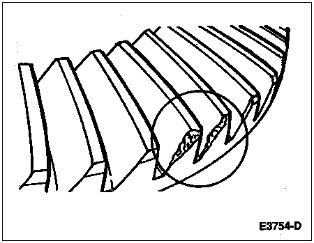
Scored Gear Teeth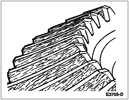
Knock
Knock, which can occur in all driving phases, has several causes. In most cases, the technician will discover one of the following conditions:
A gear tooth damaged on the drive side is a common cause of the knock. This can usually be corrected by grinding the damaged area.
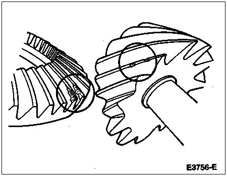
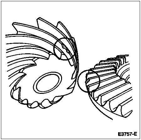
Occasionally, the rear axle differential gear case bolts (4216) will knock against the inside of the rear axle housing casting. The cause may be too little clearance due to casting flash, bumps or simply the bolts may be loose. In this case, the differential case (4204) can be removed and the interference points ground out.
NOTE: Be sure to measure the end play with a dial indicator and not by feel.
Knock is also characteristic of excessive end play in the axle shafts. Up to 0.762mm (0.030 inch) is allowed in semi-float axles. The frequency of knock will be less because the axle shaft speed is slower than the driveshaft.
Clunk, Ford Rear Axles
| Description | Tool Number |
|---|---|
| Companion Flange Holding Tool | T57T-4851-B |
| Companion Flange Holding Tool | T78P-4851-A |
Raise vehicle on hoist.
NOTE: Remove driveshaft when performing this procedure on circular rear axle universal joint flange application.
Use a rigid bar or pipe of suitable length. Clamp one end to the rear axle companion flange using Companion Flange Holding Tool T57T-4851-B for half-round rear axle companion flange on F-250 and F-350 applications, and Companion Flange Holding Tool T78P-4851-A for F-150 (circular rear axle universal joint flange).
Clamp the other end to the frame or body member in order to prevent movement of the rear axle universal joint flange.
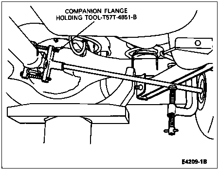
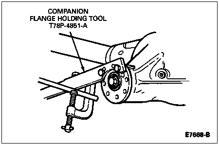
Lower the vehicle so that one rear wheel is resting on a wheel chock to prevent it from turning. The other rear wheel will then be used to measure total rear axle backlash.
Rotate the free wheel slowly, by hand, until a feel of driving the rear axle is encountered. Position a crayon or chalk firmly on the side of the tire 305mm (12 inches) from the center of the wheel. Rotate the wheel slowly in the opposite direction until the feel of driving the rear axle is encountered again.
Measure the length of the crayon or chalk mark on the tire. If the length of the mark is 25.4mm (1 inch) or less, the rear axle backlash is within allowable limits.
If the chalk mark is greater than 25.4mm (1 inch), check for these conditions:
If any or all of these conditions are present, repair or replace parts as necessary. If none of these conditions are present, there may be a loose fit of the axle shafts to the side gear splines. Continue with Steps 9-12 until the correction is made.
Install new differential side gear (4236) and check the backlash.
Install two new axle shafts.
Replace the differential case.
Install the driveshaft so the index mark on the driveshaft slip yoke (4841) is in line with the index mark on the driveshaft centering socket yoke (4782). This ensures original driveline balance. Refer to Section 05-01. If vibration exists after installation, refer to Diagnosis and Testing in Section 00-04.
Clunk, Dana Rear Axles
Apply parking brake to keep both rear wheels from turning.
Mount a Dial Indicator/Magnetic Base D78P-4201-B or equivalent on the differential carrier housing with the indicator point positioned to contact the rear axle universal joint flange 38.1mm (1-1/2 inch) from the center line of the differential pinion shaft.
With the transmission in neutral and engine not running, check the total rotational movement of the rear axle universal joint flange. If the total reading on the dial indicator is 1.9mm (0.075 inch) or less, the rear axle backlash is within allowable limits.
If total reading on the dial indicator is more than 1.9mm (0.075 inch), check for these conditions:
If any or all of these conditions are present, repair or replace parts as necessary. If none of these conditions are present, there may be a loose fit of the axle shafts to the side gear splines. Continue with Steps 6-9 until the correction is made.
Install new differential side gears and check the backlash.
Install two new axle shafts.
Replace the differential case.
Install the driveshaft so the index mark on the driveshaft slip yoke is in line with the index mark on the driveshaft centering socket yoke. This ensures original driveline balance. Refer to Section 05-01. If vibration exists after installation, refer to Diagnosis and Testing in Section 00-04.
Bearing Whine
Bearing whine is a high-pitched sound similar to a whistle. It is usually caused by malfunctioning pinion bearings, which are operating at driveshaft speed. Bearing noise occurs at all driving speeds. This distinguishes it from gear whine which usually comes and goes as speed changes.
Chatter While Turning
Chatter while turning is a condition in which the rear end vibrates. The vibration is plainly felt and may be heard as a groaning noise. In conventional axles, extra differential thrust washers cause a condition of partial lockup that creates this chatter. Chatter noise on Traction-Lok® axles can usually be traced to erratic movement between adjacent clutch plates and can be corrected with a lubricant change that includes friction modifier additive.
Click at Engagement
Click at engagement is a slight noise condition, distinct from a clunk, that occurs in reverse or drive engagement. It can be corrected by installing a rear axle drive pinion shaft oil slinger (4670) between the rear axle universal joint flange and outer differential pinion bearing (4621).
Axle Shaft Noise
Axle shaft noise is similar to gear noise and differential pinion bearing whine. Axle shaft bearing noise will normally distinguish itself from gear noise by occurring in all driving modes (drive, coast and float), and will persist with transmission in neutral while vehicle is moving at problem speed. If the vehicle makes this noise, remove suspect axle shafts, replace rear wheel bearings and install a new set of wheel seals. Re-evaluate vehicle for noise before removing any internal components.
Bearing Rumble
Bearing rumble sounds like marbles being tumbled. This condition is usually caused by a malfunctioning wheel bearing. The lower pitch is the result of wheel bearings turning at only about one-third of driveshaft speed. Wheel bearing noise also may be high-pitched, similar to gear noise, but will be evident in all four driving modes.
Analysis of Inoperative Conditions
If the axle fails to operate, there will be broken or jammed-up parts.
Broken Axle Shaft
Inspect a broken axle shaft for a twist in the spline or next to the break.
Breaks that occur away from the spline or that are not accompanied by a twist in the spline may be caused by forging flaws and/or fatigue of the axle shaft.
Conditions that can cause a broken axle shaft include forging flaws or excessive impact load to the axle shaft as a result of a collision or other factors.
Broken Welds
Rear axle housing welds, if completely broken, call for replacement of the rear axle housing.
Wheel Bearing Malfunctions
Because of the severe loads they must handle, rear wheel bearings may require replacement at high mileage. If a rear wheel bearing fails at low mileage, it is usually caused by overloading or a defect in the bearing.
Axle Lockup
Lockup or seizure of the axle shaft usually indicates inadequate lubrication. The lubricant prevents friction and helps cool the parts as they heat up. Without enough lubricant, the heated parts get soft and may eventually weld together. Check for lubricant leaks after servicing.