Section 05-00: Axle and Driveshaft, Service | 1996 F-150, F-250, F-350 4x2 and 4x4, F-Super Duty and Bronco Workshop Manual |
ADJUSTMENTS
Driveshaft Runout and Balance
Vibration or shudder which is noticeable either on fast acceleration, when coasting, or when using the engine (6007) for braking, may be caused by the rear axle housing (4010) being loose on the rear suspension, improper tire balance, improper driveline installation or driveline balance.
If driveshaft components are replaced and shaft vibration is encountered after installation, disconnect and remove the driveshaft (4602). Rotate the rear axle universal joint flange (4851) 180 degrees then reconnect the driveshaft to the driveshaft slip yoke (4841) and reinstall in vehicle. If the vibration persists, disconnect the driveshaft at the rear axle universal joint flange. Rotate the rear axle universal joint flange 180 degrees and reconnect the driveshaft to the rear axle universal joint flange. Driveshafts connected to circular rear axle universal joint flanges on 8.8-inch rear axles (4001) can be indexed in 45-degree increments to fine tune the balance of the driveline system.
If rotating the driveshaft 180 degrees does not eliminate vibration, the driveshaft may be balanced, using the following procedure:
Raise the vehicle on a twin-post hoist so that both the front and rear axles are safely supported with all wheels free to rotate.
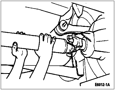
Remove the rear wheels and tires. Reinstall lug nuts (1012) to retain brake drums or rotors.
With the transmission (7003) in gear, increase the vehicle speed to the maximum vibration level. Note and record the speed of this vibration period as a baseline speed.
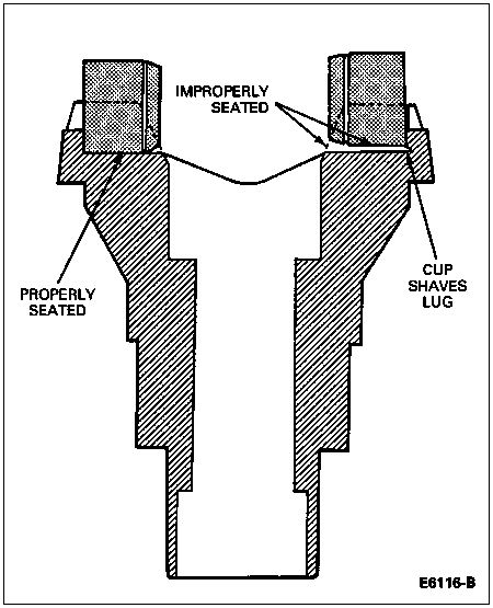
Check the attachment of all rear axle shaft universal joint bearing caps of the driveshaft to the transmission yoke for improper installation or damaged rear axle shaft universal joint bearing cap locating lugs. All yokes with worn, shaved, or damaged locating lugs must be replaced.
 WARNING: USE CAUTION WHEN CHECKING THE DRIVESHAFT NEAR THE BALANCE WEIGHTS TO
PREVENT INJURY TO THE HANDS.
WARNING: USE CAUTION WHEN CHECKING THE DRIVESHAFT NEAR THE BALANCE WEIGHTS TO
PREVENT INJURY TO THE HANDS.
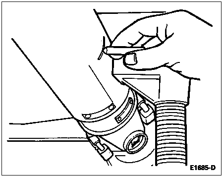
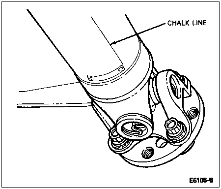
With the transmission in gear, run the vehicle with the driveshaft rotating at a speedometer speed of 64-80 km (40-50 miles); have an assistant carefully bring a crayon, piece of chalk, or colored pencil up until it just barely contacts the rear end, center and front end of the driveshaft. The chalk marks will indicate the heavy side of the driveshaft.
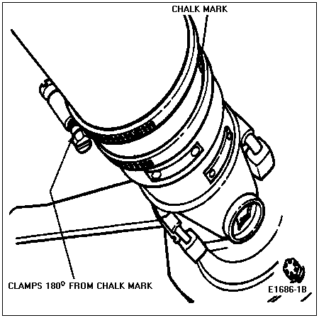
Install two screw-type hose clamps on the driveshaft so that their heads are located 180 degrees from the chalk mark, starting at the pinion yoke end of the driveshaft. Tighten the clamps.
CAUTION: To prevent overheating, do not run the vehicle on the hoist for an extended period.
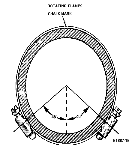
Run the vehicle up to the baseline speed. If vibration is still evidenced, rotate the clamps approximately 45 degrees away from each other and test for correction of vibration.
If necessary, continue to rotate the clamps apart in smaller increments until the vibration is eliminated or begins to be reduced.
If the vibration is not completely eliminated, repeat Steps 1-8 and balance the front end of the driveshaft, checking for elimination or reduction in the vibration level.
Reinstall wheels and tires.
Remove the vehicle from the hoist and road test.
Alternate Procedure
Road test. Evaluate and record road speed at which vibration occurs.
Raise vehicle on a frame contact hoist. Remove the wheels and tires. Reinstall lug nuts to retain brake drums or rotors. Re-evaluate by starting the engine, engaging the transmission and accelerating to the indicated speeds at which the vibration was most severe during the road test. Suspending the rear axle makes the driveline more sensitive to vibration.
Disconnect the driveshaft from the rear axle universal joint flange. Rotate the driveshaft 180 degrees from its original position and reinstall. Repeat Step 2.
In some cases, rotating the driveshaft 180 degrees may decrease the vibration to an acceptable level. However, if the vibration level is increased, install the driveshaft in its original position and proceed to Step 5. Driveshafts connected to circular rear axle universal joint flanges on 8.8-inch rear axles can be indexed in 45-degree increments to fine tune the balance of the driveline system.
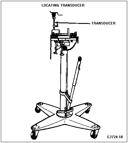
A vehicle is more sensitive to imbalance or runout at the rearward end of the driveshaft. Therefore, locate the heavy side of the driveshaft by the use of Rotunda Electronic Strobe Balancer 006-01400 or equivalent as follows:
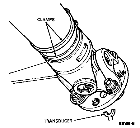
- Scribe an axial chalk line (at any radial location) approximately 101.6mm (4 inches) long at the rear of the driveshaft.
- Locate the transducer on the bottom side of the carrier, and secure it in place.
- Run the engine and driveline at the worst vibration speed noted and visually note the position of the chalk line by use of the strobe light. This provides a starting point for the initial location of the clamps.
Stop the engine and rotate the driveshaft so that the chalk line is in the same location as it was noted under the strobe light.
Install two (stainless steel) hose clamps on the driveshaft. Position the clamp heads 180 degrees from the transducer and tighten the clamps.
CAUTION: Do not run the engine with the transmission engaged on the hoist for extended periods due to the danger of overheating the engine or transmission.
Run the engine and driveline through the speed range. If no vibration is felt, remove the lug nuts, install the wheels and tires and reinstall the lug nuts in the correct position and proceed to Step 10. If any vibration still exists, the combined weight of the two hose clamp heads may be in excess. To reduce this excess weight, rotate the clamp heads away from each other approximately 15 degrees (one each way from the original position). Run the engine and driveline and note if the vibration has been reduced.
Continue to rotate the clamp heads apart in smaller angular increments until the vehicle feel of balance (vibration) is best. At this point, install the wheels and tires according to Step 8 and road test the vehicle to determine the actual degree of improvement. If satisfactory improvement has been obtained, proceed with Step 10. If no improvement has been obtained, the clamps must be removed and diagnosis should be redirected to other areas, such as wheels, tires, driveline angle and rear axle universal joint flange runout. For additional information, refer to Diagnosis and Testing in this section or Section 00-04.
When the vehicle has been corrected to a satisfactory level, as determined by a road test evaluation, tighten the clamps securely. Clean thoroughly with lacquer thinner, and spray the clamps with a commercially available black paint for a finished appearance.