Section 03-01C: Engine, 7.5L MFI
1996 F-250, F-350, F-Super Duty Chassis Cab and Motorhome Workshop Manual
REMOVAL AND INSTALLATION

Camshaft Bearings

Camshaft bearings (6261) are available prefinished to size for standard and undersize journal diameters.

SPECIAL SERVICE TOOL(S) REQUIRED
DescriptionTool Number
Camshaft Bearing SetT65L-6250-A

Removal

  1. With engine (6007) removed and placed in a work stand, remove the camshaft (6250) crankshaft, and flywheel (6375). Refer to Camshaft and to Flywheel in the In-Vehicle Service portion of this section. Push pistons to top of cylinders.

  1. Remove the camshaft rear bearing cover (6266). Refer to Engine Block Plugs service procedure in Section 03-00.

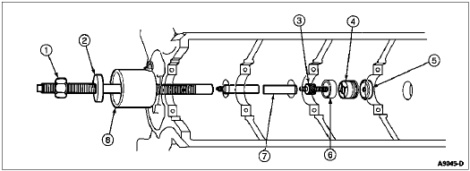
  1. Using Camshaft Bearing Set T65L-6250-A, select the proper size expanding collet and backup nut and assemble onto expanding mandrel. With the expanding collet collapsed, install the collet in the camshaft bearing. Tighten backup nut on expanding mandrel until collet fits camshaft bearing.

  1. Assemble the puller screw and extension (if necessary), as shown, and install on expanding mandrel. Wrap a cloth around threads of the puller screw to protect the front camshaft bearing or journal. Tighten pulling nut against the thrust bearing and pulling plate to remove camshaft bearing. Hold a wrench on the end of puller screw to prevent it from turning.

  1. Repeat the procedure for each camshaft bearing. To remove the front camshaft bearing, install puller screw from rear of cylinder block (6010).


Installation

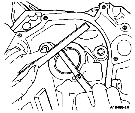
  1.  CAUTION: Failure to use correct expanding collet can cause severe bearing damage. Align oil holes in camshaft bearings with oil holes in cylinder block before pressing them into block. Be sure front camshaft bearing is installed 1.0-1.5 mm (0.040-0.060 inch) below front face of cylinder block.

    Position new camshaft bearings at bearing bores, and press in place with the tool. Be sure to center the pulling plate and puller screw to avoid bearing damage.
  1. Install a new camshaft rear bearing cover. Refer to Engine Block Plugs service procedure in Section 03-00.

  1. Install camshaft, crankshaft (6303), and flywheel. Refer to Camshaft and to Flywheel in the In-Vehicle Service portion of this section.

  1. Position piston and connecting rod on crankshaft. Tighten connecting rod nuts to 61-68 Nm (45-50 lb-ft).

  1. Install engine into vehicle. Refer to Engine in the Removal and Installation portion of this section.


    Camshaft Bearings


    ItemPart NumberDescription
    1Pulling Screw
    (Part of T65L-6250-A)
    2Pulling Plate
    (Part of T65L-6250-A)
    3Expanding Mandrel
    (Part of T65L-6250-A)
    4Expanding Collet
    (Part of T65L-6250-A)
    5Backup Nut
    (Part of T65L-6250-A)
    66262Bearing, Camshaft
    (Part Number Given Is for Reference Only)
    7Puller Screw Extension
    (Part of T65L-6250-A)
    8Front Spacer
    (Part of T65L-6250-A)
    NOTE: All Items Except No. 6 (Bearing) Are Included in Camshaft Bearing Set T65L-6250-A.