Section 03-01C: Engine, 7.5L MFI | 1996 F-250, F-350, F-Super Duty Chassis Cab and Motorhome Workshop Manual |
Description | Tool Number |
---|---|
Engine Lifting Brackets | T70P-6000 |
Removal
Drain the crankcase. Drain the cooling system. Refer to Section 03-03. Remove hood. Refer to Section 01-02.
Disconnect the battery ground cable (14301) from the battery.
Disconnect the secondary air injection manifold tube (9B449) at the right-hand side of the engine air cleaner (ACL) (9600). Perform all fuel charging system pre-service procedures. Refer to Section 03-04C.
Disconnect the air cleaner outlet tube (9B659) at the throttle body (9E926) and upper intake manifold (9424). The engine air cleaner and air cleaner outlet tubes can now be removed, after disconnecting the engine air cleaner hot air tube (9652) at the engine air cleaner.
Remove the secondary air injection silencer inlet hose (9J435) connected to the engine air cleaner hot air tube and remove the engine air cleaner hot air tube.
Remove the engine air cleaner and air cleaner outlet tube, including the crankcase ventilation hose (6853). Disconnect the fuel vapor return valve from the wiring harness connector and remove the fuel vapor return hose and valve assembly from the positive crankcase ventilation valve (PCV valve) (6A666).
Disconnect the lower radiator hose (8286) and upper radiator hose (8260) at the radiator (8005). If equipped with an automatic transmission (7003), disconnect the transmission oil cooler lines.
If so equipped, discharge the air conditioning system and remove the A/C condenser core (19712). Refer to Section 12-00 and Section 12-03A. Disconnect air conditioning lines at the A/C compressor (19703). Disconnect compressor clutch electrical lead.
Remove the fan shroud (8146) and position it over the fan blade (8600). Remove the radiator. Refer to Section 03-03. Remove the fan shroud, fan clutch (8A616), drive belts (8620) and water pump pulley (8509).
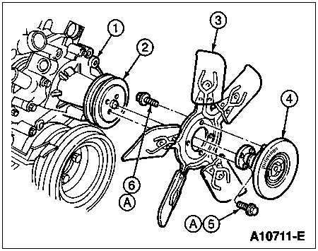
Item | Part Number | Description |
---|---|---|
1 | 8501 | Water Pump |
2 | 8509 | Water Pump Pulley |
3 | 8600 | Fan Blade |
4 | 8A616 | Fan Clutch |
5 | 380288-S2 | Screw and Washer Assembly |
6 | 57632-S2 | Screw and Washer Assembly |
A | — | Tighten to 16-24 Nm (12-18 Lb-Ft) |
Remove the generator bolts and allow the generator (GEN) (10300) to swing down and out of the way.
Disconnect throttle and transmission linkage atthrottle body and remove accelerator cable bracket (9723) from upper intake manifold. Remove the speed control hardware if so equipped.
Disconnect the wiring harness from the oil pressure sensor (9278). Disconnect evaporative emission hoses at the evaporative emissions canister (EVAP canister) (9D653).
Disconnect the fuel lines at quick disconnect couplings and vacuum lines to the intake manifold.
Disconnect EGR valve to exhaust manifold tube (9D477) at left exhaust manifold (9431) and upper intake manifold. Plug manifold opening.
Disconnect power brake booster vacuum hose, if so equipped.
Disconnect the heater hoses from the water pump (8501) and intake manifold.
Disconnect secondary air injection silencer inlet hose at diverter valve.
Remove the flywheel housing-to-engine upper bolts.
Disconnect the ground strap from the cylinder block (6010).
Remove the oil level dipstick (6750) and oil level indicator tube (6754). Refer to Oil Level Indicator Tube in the In-Vehicle Service portion of this section.
Raise the front of the vehicle. Disconnect the starter cable from the starter motor (11002). Remove the starter motor. Refer to Section 03-06A.
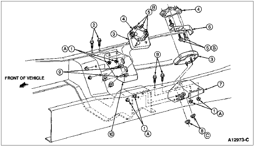
Disconnect the muffler inlet pipes from the left-hand exhaust manifold (9430) and right-hand exhaust manifold. Disconnect the front engine support insulators (6038) from the right-hand front engine support bracket (6028) and left-hand front engine support bracket (6029) on the frame underbody.
Raise the engine (6007) slightly and carefully pull it from the transmission. Carefully lift the engine out of the engine compartment so that the engine rear plate (7007) is not bent or other components damaged. Install the engine on a work stand.
Item | Part Number | Description |
---|---|---|
1 | N803203-S100 | Screw and Washer, M12-1.75 x 35 |
2 | 6038 | Front Engine Support Insulator |
3 | 6028 | Front Engine Support Bracket |
4 | N807479-S301 | Nut and Washer, M12-1.75 |
5 | 387811-S100 | Screw and Washer, 7/16-14 x 1 |
6 | 6030 | Front Engine Support Mounting Bracket |
7 | 6C038 | Engine Mount Heat Shield (Left-Hand Only) |
A | — | Tighten to 109-149 Nm (80-109 Lb-Ft) |
B | — | Tighten to 88-118 Nm (65-87 Lb-Ft) |
C | — | Tighten to 81-109 Nm (60-80 Lb-Ft) |
Item | Part Number | Description |
---|---|---|
1 | N800937-S109 | Nut |
2 | N802114-S12 | Bolt |
3 | 6038 | Front Engine Support Insulator |
4 | 6049 | Front Engine Support Mounting Bracket |
5 | 387811-S | Bolt |
6 | 6C038 | Engine Mount Heat Shield (Left-Hand Only) |
7 | 6029 | Front Engine Support Bracket (Left-Hand) |
8 | N802320-S2 | Nut |
9 | N802114-S | Bolt |
10 | 6028 | Front Engine Support Bracket (Right-Hand) |
A | — | Tighten to 58-77 Nm (43-57 Lb-Ft) |
B | — | Tighten to 81-109 Nm (60-80 Lb-Ft) |
C | — | Tighten to 96-127 Nm (71-94 Lb-Ft) |
Using a Rotunda Low Lift Transmission Jack 164-R3508 or equivalent, support transmission.
On a vehicle with automatic transmission, remove the transmission housing cover (7986). Remove the torque converter-to-flywheel attaching bolts. Remove transmission-to-engine bolts.
On vehicles with manual transmission, remove the engine rear plate from the flywheel housing. Remove the remaining flywheel housing-to-engine bolts.
Lower the vehicle, and then support the transmission. Install Engine Lifting Brackets T70P-6000 onto the right-hand front and left-hand rear engine lifting eye (17A084). Attach the engine lifting sling.
Installation
Attach Engine Lifting Brackets T70P-6000 and sling. Remove the engine from the work stand.
Lower the engine carefully into the engine compartment. Make sure the flywheel housing to block dowels (6397) in the cylinder block are through the engine rear plate. Engage flywheel housing to block dowels with holes in the flywheel housing.
On a vehicle with manual transmission, start the input shaft (7017) into the clutch disc (7550). It may be necessary to adjust the position of the transmission in relation to the engine if the input shaft will not enter the clutch disc. If the engine hangs up after the input shaft enters, turn the crankshaft (6303) slowly (transmission in gear) until the shaft splines mesh with the clutch disc splines.
Install the flywheel housing upper bolts.
Install the front engine support insulator-to-front engine support bracket nuts and washers. Tighten to 88-118 Nm (65-87 lb-ft) for F-250, F-350 and F-Super Duty, 96-127 Nm (71-94 lb-ft) for F-Super Duty Motorhome Chassis. Disconnect the engine lifting sling.
Install the remaining flywheel housing-to-engine bolts.
On a vehicle with automatic transmission, install the converter-to-flywheel attaching bolts. Install the transmission housing cover or the engine rear plate on manual transmissions.
Remove the Rotunda Low Lift Transmission Jack 164-R3508 or equivalent from the transmission and lower the vehicle. Remove the Engine Lifting Brackets T70P-6000.
Raise the front of the vehicle. Connect the muffler inlet pipes to the left exhaust manifold and right exhaust manifold. Tighten the nuts to 34-49 Nm (25-36 lb-ft).
Position and install the starter motor and the starter cable. Refer to Section 03-06A.
If so equipped, connect the air conditioning compressor magnetic clutch lead wire.
Connect the wiring harness to the oil pressure sensor.
Connect the accelerator cable bracket to the upper intake manifold. Connect the transmission and throttle linkage to the throttle body and speed control linkage, if so equipped.
Connect the fuel lines. Reconnect evaporative emission hoses at the evaporative emissions canister.
Install the water pump pulley, drive belts, fan clutch and fan blade. Position the fan shroud over the fan blade.
NOTE: When the battery has been disconnected and reconnected, some abnormal drive symptoms may occur while the powertrain control module (PCM) (12A650) relearns its adaptive strategy. The vehicle may need to be driven 16 km (10 miles) or more to relearn the strategy.
Position the generator (GEN) (10346) and install the generator bolts. Connect the battery ground cable. Adjust the drive belt tension to specification. Refer to Section 03-05.
If so equipped, connect the air conditioning lines to the A/C compressor.
Install the radiator. Refer to Section 03-03. Connect the upper radiator hose and lower radiator hose. Connect the transmission oil cooler lines, if so equipped. Install the fan shroud.
If so equipped, install the A/C condenser core to the radiator. Refer to Section 12-03A.
Perform all fuel charging system post-service procedures. Refer to Section 03-04C.
Connect the heater hoses to the water pump and intake manifold. Fill and bleed the cooling system. Refer to Section 03-03. Fill the crankcase with the proper grade and quantity of oil. Connect the booster vacuum hose, if so equipped.
Operate the engine at fast idle and check all gaskets and hose connections for leaks.
Install the engine air cleaner and air cleaner outlet tube assembly. Connect the crankcase ventilation hose to the engine air cleaner.
Install the fuel vapor return hose and valve assembly to the positive crankcase ventilation valve and connect the fuel vapor return valve to the wiring harness connector.
Install the engine air cleaner hot air tube and connect the secondary air injection silencer inlet hose.
Install the air cleaner outlet tube to the throttle body and upper intake manifold.
Connect the secondary air injection manifold tube to the right-hand side of the engine air cleaner.
Evacuate and charge the air conditioning system, if so equipped. Refer to Section 12-00.
Install hood. Refer to Section 01-02.