Section 03-01C: Engine, 7.5L MFI
1996 F-250, F-350, F-Super Duty Chassis Cab and Motorhome Workshop Manual
IN-VEHICLE SERVICE

Camshaft


Removal

  1. Drain radiator (8005) and remove. Refer to Section 03-03.

  1. Remove engine front cover (6019), timing chain, camshaft sprocket (6256) and crankshaft sprocket (6306). Refer to Timing Chain and Sprockets in the In-Vehicle Service portion of this section. Check timing chain deflection before removal. Refer to Section 03-00.
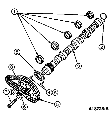


    ItemPart NumberDescription
    16261Camshaft Bearing
    26266Camshaft Rear Bearing Cover
    36250Camshaft
    442910Bolt, 1/4-20 x 1/2, Self-Locking
    56268Timing Chain
    66278Camshaft Sprocket Washer
    743001Bolt, 3/8-16 x 1.38
    86256Camshaft Sprocket
    96269Camshaft Thrust Plate
    ATighten to 11-15 Nm
    (90-135 Lb-In)
    BTighten to 54-68 Nm
    (40-50 Lb-Ft)
  1. Remove the upper and lower intake manifolds (9424). Refer to Intake Manifold, Upper, and Intake Manifold, Lower in the In-Vehicle Service portion of this section.

  1. Remove distributor. Refer to Section 03-07A.

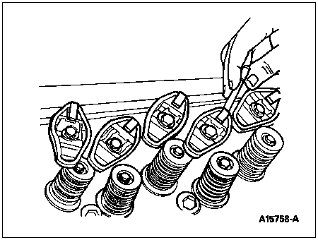
  1. Remove valve covers (6582). Back off all rocker arm seat bolts, turn rocker arms (6564) sideways, and remove the push rods (6565) keeping them in sequence.


  1. Remove the valve tappets (6500) with a magnet and place them in a rack in sequence. Rotate the valve tappets back and forth to loosen them from gum or varnish deposits.

  1. Remove the bolts attaching the A/C condenser core (19712) to the chassis, if so equipped. Carefully rest the condenser on the left fender. Secure it in this position.

  1. Remove the radiator inner grille (8150).

  1.  CAUTION: Do not nick the camshaft bearings (6261) with the camshaft lobes.

    Remove the camshaft thrust plate attaching bolts, and carefully remove the camshaft (6250) from the front of engine (6007).

  1. Refer to Section 03-00 for cleaning and inspection procedures, and repair as required.

Installation

  1. Oil the camshaft journals and apply Ford Multi-Purpose Grease D0AZ-19584-AA or equivalent meeting Ford specification ESB-M1C93-B to the camshaft lobes. Carefully slide camshaft into position. Avoid nicking the camshaft bearings with the camshaft lobes.

  1. Install camshaft thrust plate (6269). Tighten bolts to 11-15 Nm (90-135 lb-in). Check camshaft end play following procedure in Section 03-00. If end play is excessive, replace the camshaft thrust plate.

  1. Install timing chain, camshaft sprocket,crankshaft sprocket, new bolt, camshaft sprocket washer (6278) and engine front cover. Refer to Timing Chain and Sprockets in the In-Vehicle Service portion of this section.

  1. Position the radiator in the vehicle and install the upper radiator support bracket to secure radiator. Connect the lower radiator hose (8286) and upper radiator hose (8260).

  1. Install the radiator inner grille.

  1. Install A/C condenser core.

  1. Clean the valve tappets externally. Lubricate the valve tappets and valve tappet bores with specified engine oil before installing them. Lubricate the push rod ends with Ford Multi-Purpose Grease D0AZ-19584-AA or equivalent meeting Ford specification ESR-M1C159-B. Install the valve tappets and push rods in their original positions.

  1. Install upper and lower intake manifolds. Refer to Intake Manifold, Upper, and Intake Manifold, Lower, in the In-Vehicle Service portion of this section.

  1. Rotate the crankshaft vibration damper (6316) until No. 1 piston (6108) is at TDC at the end of compression stroke. Install the distributor (12127) following the procedure in Section 03-07A.

  1. Apply Ford Multi-Purpose Grease D0AZ-19584-AA or equivalent meeting Ford specification ESB-M1C93-B to valve stem tips. Position rocker arms over push rods and tighten bolts. Refer to Rocker Arm in the In-Vehicle Service portion of this section. Adjust valve clearance if necessary. Refer to Adjustments in this section.

  1. Clean the valve covers and cylinder head sealing surfaces. Position new valve cover gasket (6584), if required, in cover seal groove. Make sure the valve cover gasket tang is secured in the notch of the valve cover.

  1. Position valve cover on the cylinder head (6049) and tighten the four valve cover bolt and washer assemblies to 12-15 Nm (9-11 lb-ft), starting at the rearmost bolt and working forward.

  1. Connect heater hose at intake manifold and at water pump (8501).

  1. Install the accelerator linkage. Install the speed control linkage, if so equipped.

  1. Connect engine vacuum lines to their original outlets on the fittings of the upper and lower intake manifolds.

  1. Connect positive crankcase ventilation valve (PCV valve) (6A666) and crankcase vent connector and hose (6C324) to right valve cover.

  1. Install the distributor cap (12106) and connect the ignition coil (12029) and distributor to spark plug wires (12286).

  1. Install water pump pulley (8509) and fan clutch (8A616) to water pump hub with four bolts. Install fan blade (8600) to fan clutch with four bolts. Tighten water pump pulley, fan clutch hub bolts, and fan-to-fan clutch hub bolts to 16-24 Nm (12-18 lb-ft). Install fan shroud (8146). Install drive belt (8620) according to instructions on decal on upper radiator support bracket.

  1. Fill and bleed the cooling system. Refer to Section 03-03. Fill and bleed power steering reservoir. Refer to Section 11-00.Run engine at fast idle and check for leaks.

  1. Adjust the ignition timing to specifications listed on the engine decal.

  1. Adjust transmission linkage, if necessary. Refer to Section 07-01A or Section 07-01B. Install the engine air cleaner (ACL) (9600) and air cleaner outlet tube (9B659).