Section 05-02G: Axle, Integral Carrier, 8.8-Inch Ring Gear | 1996 F-150 and Bronco Workshop Manual |
DISASSEMBLY AND ASSEMBLY
Axle Disassembly
SPECIAL SERVICE TOOL(S) REQUIRED| Description | Tool Number |
|---|
| Impact Slide Hammer | T50T-100-A |
| Axle Wheel Bearing Puller | T83T-1225-A |
| Pinion Bearing Cone Remover | T71P-4621-B |
| Puller-Differential Side Bearing Remover | T77F-4220-B1 |
| Differential Side Bearing Replacer | T57L-4221-A2 |
Sensor, Anti-Lock Brake
Removal
Remove bolt. Remove rear brake anti-lock sensor (2C190).
Clean axle mounting surface, using caution to prevent dirt from entering rear axle housing (4010).
Observe if axle lubricant has leaked up through core or around perimeter of rear brake anti-lock sensor O-ring. Discard if leakage is present.
Companion Flange and Pinion Oil Seal Removal
Remove driveshaft (4602), pinion nut, rear axle universal joint flange (4851) and rear axle drive pinion seal (4676). Refer to Flange Yoke Seal and/or Universal Joint Flange in the Removal and Installation portion of this section. Be sure to mark driveshaft, rear axle universal joint flange, and pinion for proper assembly.
NOTE: If rear axle drive pinion seal is leaking, check the rear axle housing vent (4022). If the rear axle housing vent is plugged with dirt or debris it will cause pressure buildup in the axle which can lead to pinion or wheel seal leaks.
Axle Shaft Removal
Clean all dirt from the area of axle housing cover (4033) with a wire brush or cloth.
Drain rear axle lubricant by removing the axle housing cover.
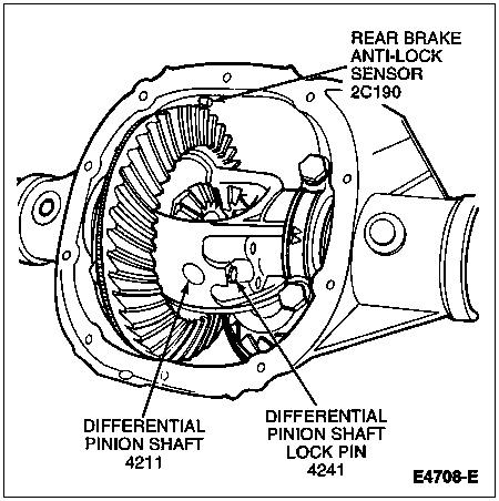
 CAUTION: Install new differential pinion shaft lock pin (4241) after removal. If new pin is not available, thoroughly clean threads of used pin and coat with Threadlock® and Sealer EOAZ-19554-AA or equivalent meeting Ford specification WSK-M2G351-A5 (Type II) before installation.
Remove differential pinion shaft lock pin and differential pinion shaft (4211).
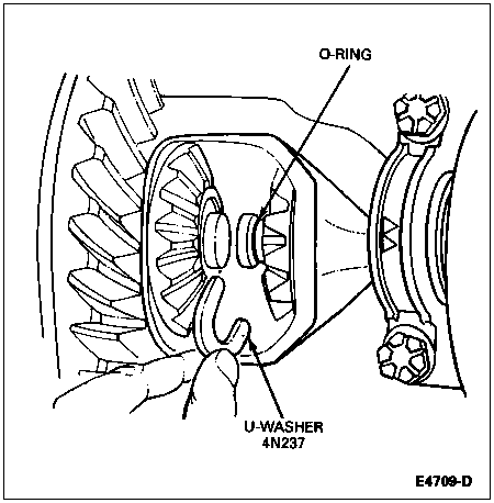
NOTE: When removing the u-washer (4N237), use care not to lose or damage the rubber O-ring which is in the axle shaft groove under the u-washer. The O-ring is used to hold the u-washer in position until the axle shafts (4234) are pulled back in place at reassembly.
Push the flanged end of the axle shafts inboard and remove the u-washer from the button end of each axle shaft.
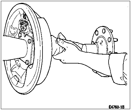
Remove the axle shaft from the rear axle housing, being careful not to damage the inner wheel bearing oil seal (1177).
Wheel Bearing and Oil Seal Removal
NOTE: If inner wheel bearing oil seal is leaking, check the rear axle housing vent. If the rear axle housing vent is plugged with dirt or debris, it will cause pressure buildup in the rear axle housing which can lead to seal leaks.
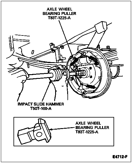
Using Impact Slide Hammer T50T-100-A and Axle Wheel Bearing Puller T83T-1225-A, insert into the bore as shown and position behind the rear wheel bearing (1225) so the tangs on the tool engage the bearing outer race. Remove the rear wheel bearing and inner wheel bearing oil seal as a unit, using the slide hammer tool.
Differential Case Removal
 CAUTION: Bearing caps MUST NOT be interchanged or rotated.
NOTE: Before removing the differential case (4204), check the ring gear runout. Refer to Inspection before Disassembly of Carrier in the Cleaning and Inspection portion of this section. If ring gear runout exceeds 0.10mm (0.004 inch), the differential case and ring gear and pinion must be removed to perform the differential case runout check. The differential runout check will isolate the cause of excessive ring gear runout. Refer to Differential Case Runout Check in the Disassembly and Assembly portion of this section.
NOTE: The direction and location of triangles on bearing caps must be noted. When reassembled the triangles must be pointing in the same direction (outboard) as before removal.
Mark one differential bearing cap to make sure the caps will be installed in their original locations and positions with triangles pointing outboard.

Loosen the differential bearing cap bolts and bearing caps.

 CAUTION: When using the pry bar in the following step, place a wood block between the pry bar and the rear axle housing to protect the differential carrier face from damage.
Pry the differential case, differential bearing cups (4222) and differential bearing shims (4067) out until they are loose in the bearing caps. Remove the bearing caps and remove the differential case from the differential carrier.

Remove the bolts that attach the ring gear to the differential case. Remove the ring gear from the differential case by striking at alternate holes around the gear. Use a punch that is small enough to hit the bottom of the tapped holes and not damage the threads. Use care to prevent damage to ring gear teeth. Support the ring gear while removing the bolts so the ring gear does not fall and nick any teeth.

NOTE: The ring gear can be removed and installed without removing the anti-lock speed sensor ring.
On vehicles equipped with an anti-lock speed sensor ring, remove the ring gear bolts. Remove ring gear by striking at alternate holes around the gear. Support the ring gear to prevent nicked teeth.
Remove the anti-lock speed sensor ring with a soft-faced hammer. Discard anti-lock speed sensor ring. Once removed, the anti-lock speed sensor ring cannot be reused. A new anti-lock speed sensor ring must be installed.

Drive Pinion Removal
SPECIAL SERVICE TOOL(S) REQUIRED| Description | Tool Number |
|---|
| Pinion Bearing Cone Remover | T71P-4621-B |
With a soft-faced hammer, drive the pinion out of the outer drive pinion bearing cup and remove it through the rear of the differential carrier.
To remove the differential pinion bearing (4630) assembly, use Pinion Bearing Cone Remover T71P-4621-B as shown.

Measure the drive pinion bearing adjustment shim (4663), which is found under the differential pinion bearing, with a micrometer and record the thickness (as a reference to be compared to the shim gauge reading prior to installing the differential pinion bearing).
Pinion Bearing Cup Removal
NOTE: Do not remove the drive pinion bearing cups from the carrier casting unless the drive pinion bearing cups are damaged.
If the drive pinion bearing cups are to be replaced, tap alternately (with a brass drift of suitable length) on the opposite side of the drive pinion bearing cups during removal to prevent drive pinion bearing cups from cocking in the casting.
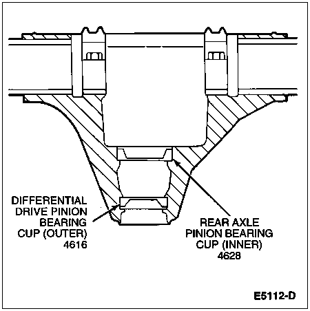
Differential Case Runout Check
If the ring gear runout check (before disassembly) exceeds specification (0.101mm [0.004 inch]), the condition may be caused by a warped ring gear, a damaged differential case, excessively worn differential bearings (4221) or foreign material between mating surfaces (burrs, shavings, etc.). To determine the cause of excessive runout, proceed as follows:
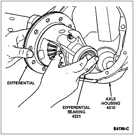
Remove the differential case from the rear axle housing. (Refer to Differential Case Removal and Drive Pinion Removal in the Disassembly and Assembly portion of this section.) Remove the bolts that attach the ring gear to the differential case. Remove the ring gear from the differential case with a hammer and drift.
Install the differential with the differential bearing shims and differential bearing cups. Tighten the bearing cap bolts to 95-115 Nm (70-85 lb-ft).
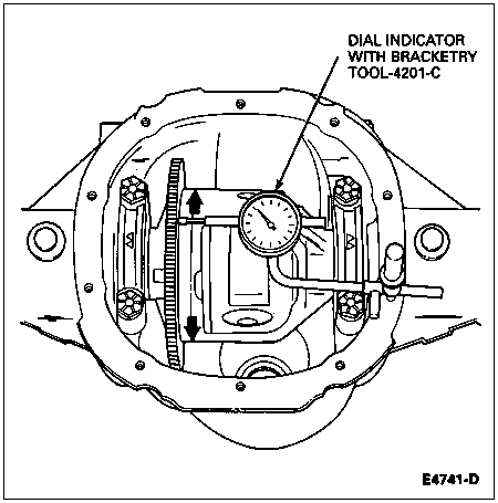
Check the runout of the differential case flange with a Dial Indicator with Bracketry TOOL-4201-C or equivalent. If the runout is within specification (maximum 0.076mm [0.003 inch]), install a new differential ring gear and pinion (4209). If the runout exceeds specification, the ring gear is true and the concern is due to either a damaged differential case or differential bearings. Visually inspect the differential bearings. If differential bearings are not damaged, replace both the differential case and differential bearings. Recheck the runout with new parts. Visually inspect the anti-lock speed sensor ring for damage and replace if required.
Remove the differential case from the integral carrier and remove the differential bearings from the differential case using Differential Side Bearing Puller T77F-4220-B1.
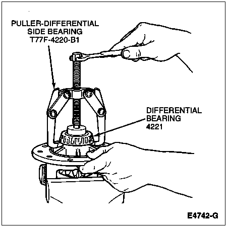
NOTE: During installation, press against the bearing cone only.
Install new differential bearings on the case hubs using Differential Side Bearing Replacer T57L-4221-A2 and install the differential (4026) in the carrier without the ring gear.
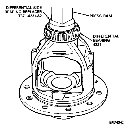
Check the case runout again with the new differential bearings. If the runout is now within 0.076mm (max. 0.003 inch), use the new differential bearings for assembly. If the runout is still excessive, the differential case is damaged and should be replaced.

![]() CAUTION: Install new differential pinion shaft lock pin (4241) after removal. If new pin is not available, thoroughly clean threads of used pin and coat with Threadlock® and Sealer EOAZ-19554-AA or equivalent meeting Ford specification WSK-M2G351-A5 (Type II) before installation.
CAUTION: Install new differential pinion shaft lock pin (4241) after removal. If new pin is not available, thoroughly clean threads of used pin and coat with Threadlock® and Sealer EOAZ-19554-AA or equivalent meeting Ford specification WSK-M2G351-A5 (Type II) before installation.


