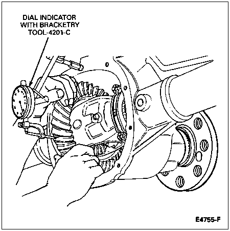
Set up a dial indicator and check ring gear backlash and ring gear backface runout. Backlash should be 0.20-0.38mm (0.008-0.015 inch) (0.30-0.38mm [0.012-0.015 inch] preferred).

Section 05-02G: Axle, Integral Carrier, 8.8-Inch Ring Gear | 1996 F-150 and Bronco Workshop Manual |
| Description | Tool Number |
|---|---|
| Pinion Depth Gauge | T79P-4020-A |
The differential and drive pinion should be inspected before they are removed from the carrier. These inspections can determine the cause of the concern and the resolution.
Wipe the lubricant from the internal working parts and visually inspect the parts for wear or damage.
Rotate the gears to see if there is any roughness which would indicate damaged bearings or gears.
Check the ring gear teeth for signs of scoring, abnormal wear, nicks or chips.
Set up a dial indicator and check ring gear backlash and ring gear backface runout. Backlash should be 0.20-0.38mm (0.008-0.015 inch) (0.30-0.38mm [0.012-0.015 inch] preferred).

NOTE: There is a space provided between the anti-lock speed sensor ring and the ring gear for measuring ring gear backface runout.
Check ring gear backface runout. To check ring gear backface runout, mount Dial Indicator with Bracketry TOOL-4201-C or equivalent on the carrier so the tip of the dial indicator contacts the backface of the ring gear. Backface runout should be no more than 0.101mm (0.004 inch).

A contact pattern may not always be an acceptable guide to check for noise. However, if the pattern is incorrect, the axle will probably be noisy. Refer to Section 05-00 for contact pattern example. Proper gearset assembly must be checked using the Pinion Depth Gauge T79P-4020-A set which shows the correct pinion shim required to make sure an acceptable running condition is achieved. Refer to Axle Assembly in this section.