Section 05-02G: Axle, Integral Carrier, 8.8-Inch Ring Gear | 1996 F-150 and Bronco Workshop Manual |
Description | Tool Number |
---|---|
Pinion Bearing Cone Remover | T71P-4621-B |
Removal
NOTE: This procedure includes removal (transfer) of differential ring gear and pinion (4209).
Raise vehicle and install safety stands. Remove rear wheels and tires. Refer to Section 04-04.
Remove brake drums (1126). Refer to Section 06-02.
Remove driveshaft (4602), rear axle universal joint flange (4851) and rear axle drive pinion seal (4676).
Remove rear axle shafts (4234).
Inspect rear carrier. Refer to Inspection Before Disassembly of Carrier in the Cleaning and Inspection portion of this section.
CAUTION: Bearing caps MUST NOT be interchanged or rotated.
NOTE: The direction and location of triangles on bearing caps must be noted. When reassembled, the triangles must be pointing in the same direction (outboard) as before removal.
Mark one differential bearing cap to make sure the caps will be installed in their original locations and positions with triangles pointing outboard.
Loosen the differential bearing cap bolts and bearing caps.
CAUTION: When using the pry bar in the following step, place a wood block between the pry bar and the rear axle housing (4010) to protect the differential carrier face from damage.
Pry the differential case (4204), differential bearing cups (4222) and differential bearing shims (4067) out until they are loose in the bearing caps. Remove the bearing caps and remove the differential case from the carrier.
NOTE: If replacing the rear axle housing, it may be necessary to install new pinion bearings and cups (inner and outer).
With a soft-faced hammer, drive the pinion out of the outer differential pinion bearing and remove it through the rear of the differential carrier. Remove outer differential pinion bearing (4621).
Remove the inner differential pinion bearing (4630) using the Pinion Bearing Cone Remover T71P-4621-B.
Measure the pinion shim, which is found under the differential pinion bearing, with a micrometer and record the thickness (as a reference to be compared to the pinion shim gauge reading prior to installing the rear pinion bearing).
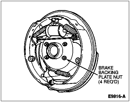
Remove the four retaining nuts from each brake backing plate (2211) and wire the brake backing plates to the underbody.
Disconnect the rear axle hose (4090) from the rear axle housing vent (4022) and the rear axle housing vent from the rear axle housing.
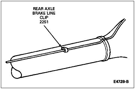
Disengage the brake tubing from the rear axle brake line clips (2251) that retain the brake tubing to the axle housing.
Position the hydraulic brake hose junction block away from the axle housing. Do not open the brake tubing.
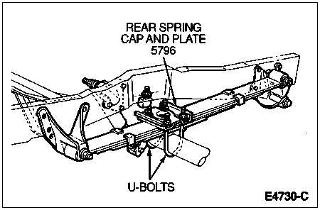
Support the rear axle housing on a jack, and then remove the U-bolt nuts. Remove the U-bolts and plates.
Remove both stabilizer U-bolts and nuts. Remove stabilizer bar bracket assemblies. Refer to Section 04-02.
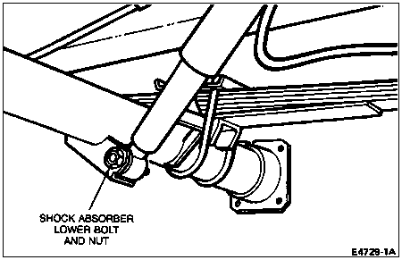
Disconnect the shock absorber lower bolts from the mounting brackets on the axle housing.
Remove the rear axle housing from the vehicle.
Installation
Raise the rear axle housing into position so the rear spring plates (5796) can be installed. Tighten the U-bolts to specification. Refer to Section 04-02 (specifications vary depending on the vehicle).
Connect the shock absorber lower bolts to the mounting bracket on the rear axle housing. Install the attaching nuts and tighten to specification. Refer to Section 04-02. Remove support jack from under axle housing.
Install stabilizer bar brackets, bar and U-bolts. Tighten nuts to 40-57 Nm (30-40 lb-ft). Refer to Section 04-02.
Insert the rear axle housing vent into the brake junction block and position the assembly over the housing vent hole. Hand-start the rear axle housing vent and tighten to 11-25 Nm (8-18 lb-ft).
Position the brake tubing to the rear axle housing and secure with the rear axle brake line clips at the right-hand axle tube and rear axle housing vent through the brake junction block.
Install the brake backing plates on the axle housing flanges (no gaskets required). Tighten the attaching nuts to 28-54 Nm (20-40 lb-ft).
Perform inspection of rear carrier. Refer to Inspection After Disassembly of Carrier in the Cleaning and Inspection portion of this section.
Check and set pinion depth. Install pinion, bearings, oil seal and rear axle universal joint flange. Refer to Flange Yoke Seal and/or Universal Joint Flange, Rear Axle in the Removal and Installation portion of this section and set pinion torque preload. Refer to Drive Pinion Shim Selection in the Disassembly and Assembly portion of this section to check preload and runout.
With pinion depth set and pinion installed, place differential case (with ring gear, anti-lock speed sensor ring, differential pinion thrust washers (4230), differential side gears, differential bearings) in carrier. Refer to Differential Case Installation in the Disassembly and Assembly portion of this section.
Install axle shafts. Refer to Axle Shaft in the Removal and Installation portion of this section. If installing new axle bearings and seals, refer to Wheel Bearing and Oil Seal in the Disassembly and Assembly portion of this section.
Install driveshaft. Refer to Flange Yoke Seal and/or Universal Joint Flange, Rear Axle in the Removal and Installation portion of this section.
Install rear axle housing cover (4033), bolts, and add fluid. Refer to Cover Installation in this section. Refer to Lubricant Capacities in the Specifications portion of this section.
Install rear brake drums. Refer to Section 06-02.
Install rear wheels and tires. Refer to Section 04-04.
Remove safety stand, and lower vehicle.
Road test.