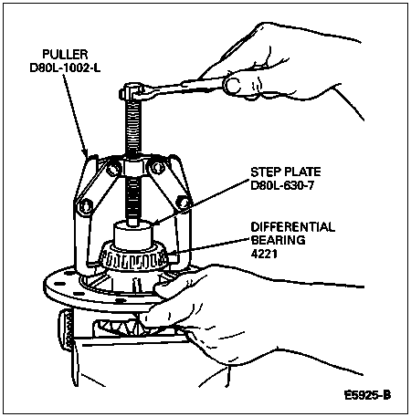
Remove the differential case (4204) from the rear axle housing (4010), and remove the differential bearings from the case using Puller D80L-1002-L and Step Plate D80L-630-7 or equivalents.

Section 05-02A: Axle, 10.25-Inch Ring Gear | 1996 F-250 Light Duty (Semi-Float), F-250 HD and F-350 (Full-Float) Workshop Manual |
Disassembly
Refer to Inspection Before Disassembly in the Cleaning and Inspection portion of this section.
If required, remove the ring gear, anti-lock speed sensor ring, differential side gears (4236), differential pinion gears (4215) and thrust washers.
Remove the differential case (4204) from the rear axle housing (4010), and remove the differential bearings from the case using Puller D80L-1002-L and Step Plate D80L-630-7 or equivalents.

Refer to Inspection After Disassembly in the Cleaning and Inspection portion of this section.
Assembly
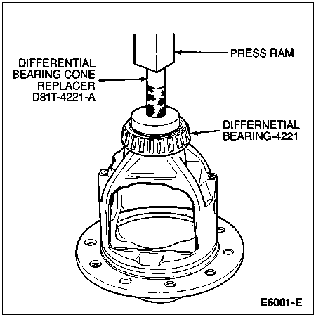
Install differential bearings on the rear hubs (1109) using Differential Bearing Cone Replacer D81T-4221-A or equivalent. Press against the bearing cone only.

![]() CAUTION: Before performing the following step, refer to Drive Pinion Shim Selection in the Removal and Installation portion of this section for installation of ring gear and anti-lock speed sensor ring.
CAUTION: Before performing the following step, refer to Drive Pinion Shim Selection in the Removal and Installation portion of this section for installation of ring gear and anti-lock speed sensor ring.
![]() CAUTION: Extreme care should be taken not to scratch, dent, chip or otherwise cause damage to speed sensor ring or teeth while handling or during assembly.
CAUTION: Extreme care should be taken not to scratch, dent, chip or otherwise cause damage to speed sensor ring or teeth while handling or during assembly.
Press the ring gear and anti-lock speed sensor ring onto the differential case, and install the attaching bolts. Tighten the bolts to 136-163 Nm (100-120 lb-ft).