The axle vent is secured to the housing assembly through the brake hose junction block. Disconnect the vent hose from the vent and the vent from the rear axle housing.

Section 05-02A: Axle, 10.25-Inch Ring Gear | 1996 F-250 Light Duty (Semi-Float), F-250 HD and F-350 (Full-Float) Workshop Manual |
Removal
Raise the vehicle and install safety stands. Remove the rear wheels and tires and the brake drums.
Remove rear anti-lock sensor hold-down bolt, and carefully remove rear brake anti-lock sensor (2C190). Refer to Sensor, Anti-Lock Brake, in the Removal and Installation portion of this section.
Mark the driveshaft axle end flange and the rear axle companion flange to make sure driveshaft (4602) is positioned properly during assembly. Disconnect the driveshaft from the rear axle companion flange. Remove the driveshaft.
Remove axle shafts (4234) (semi-floating axle) or rear hub (1109) (full-floating axle).
Disconnect brake lines at wheel cylinders.
Remove the four retaining nuts from each backing plate.
The axle vent is secured to the housing assembly through the brake hose junction block. Disconnect the vent hose from the vent and the vent from the rear axle housing.

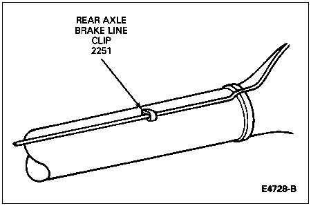
Disengage the brake line from the clips that retain the line to the axle housing and carrier.

Remove the hydraulic brake hose junction block and brake lines from the axle housing.

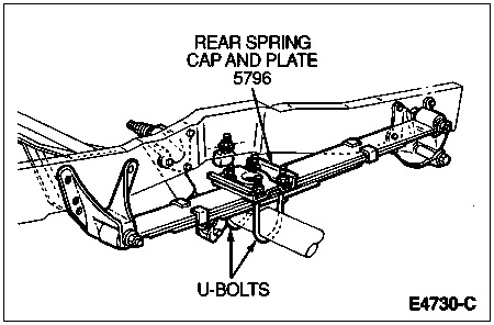
Support axle housing on a jack, and then remove the U-bolt nuts. Remove the U-bolts and plates.
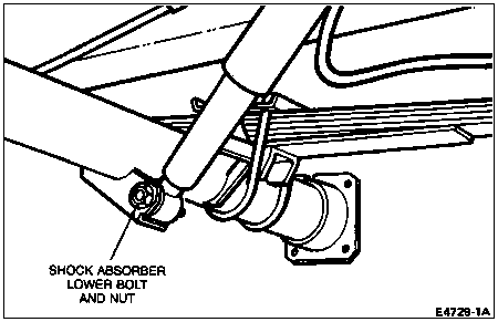
Disconnect the shock absorber lower bolts from the mounting brackets on the axle housing.
Remove the axle housing from the vehicle.


Installation
Raise the axle housing into position so that the rear spring plates (5796) can be installed. Tighten the U-bolt nuts to specification. Refer to Section 04-02.

Connect the shock absorber lower bolts to the mounting bracket on the axle housing. Install the attaching nuts and tighten to specification. Refer to Section 04-02.
Insert the vent fitting into the brake hose junction block and position the assembly over the housing vent hole. Hand-start the vent fitting and tighten to 20 Nm (15 lb-ft).
Position the brake lines to the axle housing and secure with the retaining clips at the right axle tube and vent fitting through the brake hose junction block. Attach brake lines to wheel cylinders and bleed brake system. Refer to Section 06-00.

Install the brake backing plates on the rear axle housing flanges (no gaskets required). Tighten the attaching bolts to 68-115 Nm (50-85 lb-ft).
Align the paint or scribe marks on the rear axle universal joint flange (4851) and driveshaft and connect the driveshaft. Tighten attaching bolts and nuts to 11-20 Nm (8-15 lb-ft).
Install rear brake anti-lock sensor. Refer to Sensor, Anti-Lock Brake, in the Removal and Installation portion of this section.
Install the brake drums.
Install the wheel and tire assembly. Tighten the lug nuts (1012) to 100-180 Nm (74-133 lb-ft) for five lug axles or 170-230 Nm (126-170 lb-ft) for eight lug axles. Install the wheelcovers.
Check rear axle fluid level. Refer to Specifications at the end of this section.