Section 03-01C: Engine, 7.5L MFI | 1996 F-250, F-350, F-Super Duty Chassis Cab and Motorhome Workshop Manual |
Description | Tool Number |
---|---|
Spark Plug Wire Remover | T74P-6666-A |
Crankshaft Damper Remover | T58P-6316-D |
Removal
Remove the engine (6007) and install it on a work stand.
Disconnect the distributor to spark plug wires (12286) from the spark plugs (12405) using Spark Plug Wire Remover T74P-6666-A. Remove the spark plugs to allow easy rotation of crankshaft (6303).
Remove the oil bypass filter (6714). Slide water pump bypass clamp toward the water pump (8501).
Remove the crankshaft pulley (6312) from the crankshaft vibration damper (6316).
Remove the bolt and washer from the end of the crankshaft. Install Crankshaft Damper Remover T58P-6316-D or Rotunda Gear and Pulley Puller 014-00293 or equivalent on the crankshaft vibration damper and remove crankshaft vibration damper. Remove Woodruff key.
Slide crankshaft damper spacer off crankshaft.
Remove the engine front cover (6019) and water pump as an assembly. Check the timing chain deflection. Refer to Section 03-00. Remove the timing chain, camshaft sprocket (6256) and crankshaft sprocket (6306). Refer to Timing Chain and Sprockets in the In-Vehicle Service portion of this section.
Invert the engine on a work stand. Remove the flywheel (6375) and the engine rear plate (7007). Remove the oil pan (6675) and oil pan gasket (6710). Remove the oil pump (6600).
Make sure all bearing caps (crankshaft main and connecting rod) are marked for installation into their original locations.
Turn the crankshaft until the connecting rod (6200) from which connecting rod bearing cap is being removed is up, then remove the connecting rod bearing cap. Push the connecting rod and piston (6108) assembly down into the cylinder. Repeat this procedure until all connecting rod bearing caps are removed.
Remove the crankshaft main bearing caps.
CAUTION: Handle the crankshaft with care to avoid possible fracture or damage to finished surfaces.
Carefully lift the crankshaft out of the cylinder block (6010) so thrust bearing surfaces are not damaged.
Refer to Section 03-00 for cleaning and inspection procedures. Clean the crankshaft vibration damper.
To refinish journals and dress minor imperfections refer to Section 03-00.
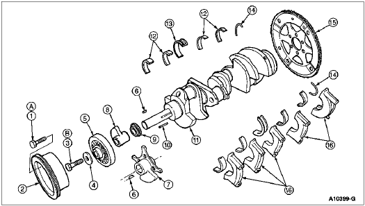
Item | Part Number | Description |
---|---|---|
1 | 42998-S8 | Bolt |
2 | 6312 | Crankshaft Pulley |
3 | 376706-S | Bolt |
4 | 6378 | Washer |
5 | 6316 | Crankshaft Vibration Damper |
6 | 74151-S | Key |
7 | 6M265 | Spacer/Trigger Wheel |
8 | 6359 | Crankshaft Damper Hub |
9 | 6306 | Crankshaft Sprocket |
10 | 388907-S | Key |
11 | 6303 | Crankshaft |
12 | 6333 | Crankshaft Main Bearing |
13 | 6337 | Crankshaft Thrust Main Bearing |
14 | 6701 | Crankshaft Rear Oil Seal (Upper and Lower Halves) |
15 | 6375 | Flywheel |
16 | — | Crankshaft Main Bearing Caps (Part of 6010) |
A | — | Tighten to 54-71 Nm (40-53 Lb-Ft) |
B | — | Tighten to 95-122 Nm (70-90 Lb-Ft) |
Installation
Remove the crankshaft rear oil seal (6701) from cylinder block and rear crankshaft main bearing cap.
Remove the crankshaft main bearings (6333) from the cylinder block and crankshaft main bearing caps.
Remove the connecting rod bearings (6211) from the connecting rods and connecting rod bearing caps.
NOTE: If the original crankshaft main bearings and crankshaft thrust main bearings (6337) are to be reused, all crankshaft main bearings and crankshaft thrust main bearings should be marked for installation into their original locations.
If the crankshaft main bearing journals have been refinished to a definite undersize, install the correct undersize crankshaft main bearing and crankshaft thrust main bearing. Make sure crankshaft main bearings and crankshaft thrust main bearings and bearing bores are clean. Foreign material under crankshaft main bearings and crankshaft thrust main bearings will distort the crankshaft main bearings and crankshaft thrust main bearings and cause failure.
CAUTION: The oil holes in the upper half of the crankshaft main bearings and crankshaft thrust main bearings must be aligned with the oil holes in the cylinder block.
Place the upper half of the crankshaft main bearings and crankshaft thrust main bearings in the bores with tang in slot.
Install lower half of the crankshaft main bearings and crankshaft thrust main bearings in crankshaft main bearing caps.
Clean the rear journal oil seal groove and mating surfaces of the cylinder block and rear crankshaft main bearing cap.
Install a new crankshaft rear oil seal in the cylinder block and rear crankshaft main bearing cap. Refer to Crankshaft Rear Oil Seal in the In-Vehicle Service portion of this section.
Carefully lower the crankshaft into place. Be careful not to damage crankshaft main bearing and crankshaft thrust main bearing surfaces.
Check the clearance of each crankshaft main bearing and crankshaft thrust main bearing with Plastigage® or equivalent. Refer to Section 03-00.
After crankshaft main bearings and crankshaft thrust main bearings have been fitted, apply light coat of specified engine oil to journals and crankshaft main bearings and crankshaft thrust main bearings. Install all crankshaft main bearing caps except thrust bearing cap No. 3. Make sure crankshaft main bearing caps are installed in original locations. Tighten the bearing cap bolts to 129-142 Nm (95-105 lb-ft).
Install the crankshaft thrust main bearing cap with bolts finger-tight.
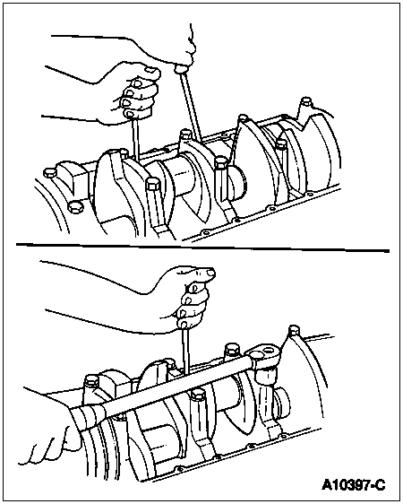
Pry the crankshaft forward against thrust surface of upper half of crankshaft thrust main bearing.
Hold crankshaft forward and pry thrust bearing cap to rear. This aligns the rear thrust surfaces of both halves of crankshaft thrust main bearing.
Retain forward pressure on the crankshaft. Tighten crankshaft main bearing cap bolts to 129-142 Nm (95-105 lb-ft).
Force the crankshaft toward the rear of engine.
Check the crankshaft end play. Refer to Section 03-00.
Install new connecting rod bearings in the connecting rods and connecting rod bearing caps. Check clearance of each connecting rod bearing with Plastigage® or equivalent. Refer to Section 03-00. Also, refer to Specifications in this section.
After the connecting rod bearings have been fitted, apply light coat of specified engine oil to journals and connecting rod bearings.
Install the connecting rod bearing cap. Make sure connecting rod bolt heads are properly seated in connecting rod. Tighten nuts to 61-68 Nm (45-50 lb-ft).
After piston and connecting rod assemblies have been installed, check side clearance between connecting rods on each crankshaft journal. Refer to Specifications in this section.
Install timing chain, camshaft sprocket and crankshaft sprocket, crankshaft damper spacer, engine front cover and crankshaft vibration damper. Refer to Timing Chain and Sprockets in the In-Vehicle Service portion of this section.
Install the engine rear plate. Position flywheel on crankshaft flange. Install and tighten the bolts to 103-115 Nm (75-85 lb-ft).
Clean the oil pan, oil pump and oil pump screen cover and tube (6622). Prime the oil pump by filling inlet port with engine oil and rotating oil pump intermediate shaft (6A618) to distribute oil within oil pump housing. Install oil pump and oil pan. Refer to Oil Pan/Oil Pump Screen Cover and Tube in the In-Vehicle Service portion of this section.
Install the oil bypass filter.
Install the spark plugs and connect the distributor to spark plug wires.
Install the engine in vehicle. Refer to Engine in the Removal and Installation portion of this section.