Section 03-01C: Engine, 7.5L MFI | 1996 F-250, F-350, F-Super Duty Chassis Cab and Motorhome Workshop Manual |
Removal
Disconnect the battery ground cable (14301).
Drain the cooling system. Refer to Section 03-03.
Remove the engine air cleaner (ACL) (9600) and air cleaner outlet tube (9B659).
Remove fan shroud (8146), fan blade (8600) and water pump pulley (8509).
Disconnect throttle body linkage and wiring.
Disconnect vacuum lines from upper and lower intake manifolds (9424). Tag lines to aid in reassembly.
Perform fuel system pre-service. Refer to Section 03-04C. Using Spring Lock Coupling Disconnect Tool D87L-9280-A and -B or equivalent, disconnect fuel supply and return lines.
Disconnect the upper radiator hose (8260) and lower radiator hose (8286).
Disconnect the two transmission oil cooler lines at the radiator (8005).
Remove the power steering pump (3A674) and position out of the way.
Disconnect the front engine support insulators (6038) from the front engine support brackets.
If so equipped, rotate air conditioner lines (at rear of A/C compressor (19703)) down to clear the dash. Remove A/C compressor without disconnecting hoses and set out of the way.
Raise the vehicle on a hoist, drain the crankcase, and remove the oil bypass filter (6714).
Remove the muffler inlet pipe assembly. Disconnect the manual kickdown linkage from the transmission (7003).
Remove the driveshaft (4602) and coupling shaft assembly. Remove the oil filler tube (7A228) assembly.
Remove the oil level dipstick (6750) and oil level indicator tube (6754) from the oil pan (6675). Refer to Oil Level Indicator Tube in the In-Vehicle Service portion of this section. Place a transmission jack under the engine oil pan. Insert a wood block between the jack surface and the oil pan. Jack the engine (6007) upward, pivoting about the rear mount until the transmission contacts the floorpan. Then, block the engine in position at the engine front supports. The engine must remain centralized to obtain the maximum height. The engine must be raised 102mm (four inches) at the engine front supports to remove the oil pan.
Remove the oil pan retaining bolts and oil pan flange reinforcement (6A674). Lower the oil pan. Remove the oil pump and pickup tube attachments. Drop the oil pump (6600) and oil pump screen cover and tube (6622) into the oil pan. Remove the oil pan rearward from the vehicle.
Installation
Clean the oil pan gasket surface at the cylinder block (6010). Clean the oil pan assembly, the oil pump screen cover and tube. Prime the oil pump by filling the inlet opening with oil and rotate the oil pump intermediate shaft (6A618) until oil emerges from the outlet opening.
Lightly apply Gasket Maker E2AZ-19562-B or equivalent meeting Ford specification WSK-M2G348-A5 to the cylinder block surface and a 6mm (1/4-inch) diameter bead to engine front cover (6019) and rear main bearing cap as shown. Also apply a bead at the parting line of engine front cover and cylinder block. Position the one-piece silicone oil pan gasket (6710) to the cylinder block and press lightly until oil pan gasket sticks to surface. Position the oil pan with oil pump and oil pump screen cover and tube to the chassis. Install the oil pump and oil pump screen cover and tube to the cylinder block. Tighten attaching bolts to 30-43 Nm (22-32 lb-ft).
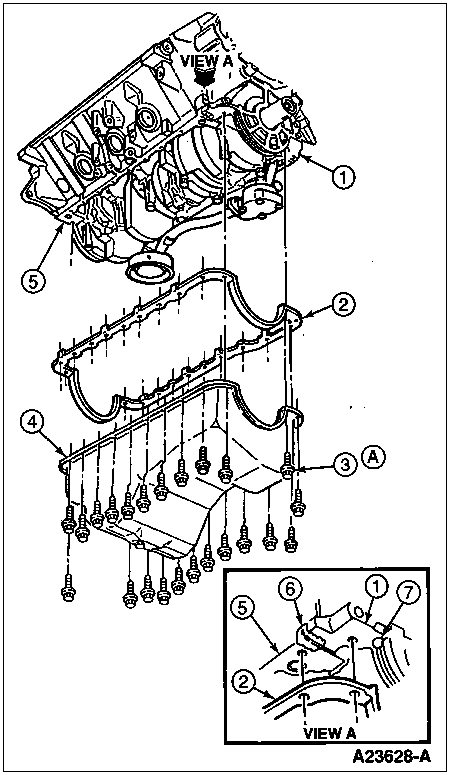
Item | Part Number | Description |
---|---|---|
1 | 6019 | Engine Front Cover |
2 | 6710 | Oil Pan Gasket |
3 | 391496-S2 | Bolt |
4 | 6675 | Oil Pan |
5 | 6010 | Cylinder Block |
6 | E2AZ-19562-B | Gasket Maker (2 Places) |
7 | E2AZ-19562-B | Gasket Maker (4 Places) |
A | — | Tighten to 11-16 Nm (8-12 Lb-Ft) |
Position the oil pan to the cylinder block position oil pan flange reinforcement and install the attaching bolts. Tighten 1/4-inch bolts to 11-16 Nm (8-12 lb-ft).
Place jack under engine and raise engine enough to remove blocks.
Lower engine and remove jack.
Install the oil level indicator tube and oil level dipstick. Refer to Oil Level Indicator Tube in the In-Vehicle Service portion of this section.
Reposition the air conditioner lines, if so equipped. If removed, reinstall A/C compressor.
Install the front engine support insulator-to-front engine support bracket retaining nuts. Tighten nuts to 96-127 Nm (71-94 lb-ft). Connect the manual kickdown linkage at the transmission. Install the driveshaft and coupling shaft assembly, and the muffler inlet pipe assembly.
Clean the oil filter mounting surface and install the oil bypass filter.
Lower the vehicle from the hoist.
Install the radiator and connect the two transmission oil cooler lines.
Install the fan blade and fan shroud, and then connect the lower radiator hose and upper radiator hose.
Connect vacuum lines to upper and lower intake manifold.
Connect the throttle and transmission linkage at the throttle body (9E926).
Install the power steering pump and drive belt (8620).
Install the engine air cleaner and air cleaner outlet tube.
Fill and bleed the cooling system. Refer to Section 03-03.
NOTE: When the battery (10655) has been disconnected and reconnected, some abnormal drive symptoms may occur while the powertrain control module (PCM) (12A650) relearns its adaptive strategy. The vehicle may need to be driven 16 km (10 miles) or more to relearn the strategy.
Connect the battery ground cable.
Fill the crankcase with engine oil. Start the engine and check for leaks.