Section 03-01C: Engine, 7.5L MFI | 1996 F-250, F-350, F-Super Duty Chassis Cab and Motorhome Workshop Manual |
Removal
Disconnect the negative battery cable. For additional information, refer to Section 14-01.
Drain the cooling system. For additional information, refer to Section 03-03.
Disconnect the air inlet hoses from the air box to the throttle body and disconnect the air by-pass hose from the air by-pass valve. For additional information, refer to Section 03-12.
Loosen the bolts attaching the fan to the water pump pulley. Loosen all drive belts and leave the belts around the water pump pulley.
Remove the bolts attaching the fan to the water pump and the bolts attaching the shroud to the radiator. Remove the fan, shroud, pulley, and belts.
Remove the belt tensioner from the A/C bracket and disconnect the locator for the distributor harness.
Disconnect the wiring connector from the A/C compressor. Remove the four bolts and one nut attaching the A/C compressor mounting bracket to the cylinder head and the water pump. Do not remove the A/C compressor or the power steering pump from the A/C compressor mounting bracket. Position the assembly aside.
Remove the three bolts attaching the alternator adjusting arm bracket to the water pump. Remove the four bolts attaching the alternator mounting bracket to the cylinder head, the cylinder block, and the water pump. Position the bracket aside and secure.
Disconnect the heater hose. Loosen the by-pass hose and lower radiator hose clamps at the water pump.
Remove the remaining water pump attaching bolts and remove the water pump from the engine front cover. Remove the water pump cover from the water pump. Discard the water pump housing gasket and the water pump cover gasket.
Remove any gasket material from the water pump, the cylinder front cover, and the separator plate mating surfaces.
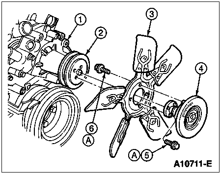
Item | Part Number | Description |
---|---|---|
1 | 8501 | Water Pump |
2 | 8509 | Water Pump Pulley |
3 | 8600 | Fan Blade |
4 | 8A616 | Fan Clutch |
5 | 380288-S2 | Screw and Washer Assy |
6 | 57632-S2 | Screw and Washer Assy |
A | — | Tighten to 16-24 Nm (12-18 Lb-Ft) |
Installation
Position a new water pump housing gasket and a new water pump cover gasket coated on both sides with Perfect Seal Sealing Compound B5A-19554-A or equivalent water-resistant sealer meeting Ford specification ESE-M4G115-A.
Position the water pump and the water pump cover onto the engine front cover. Install the bolts and tighten to 24 Nm (18 lb-ft).
Connect the heater hose, the by-pass hose, and the lower radiator hose. Tighten the clamps securely.
Install the alternator mounting bracket to cylinder head, cylinder block and the water pump with four attaching bolts. Tighten the bolts 54 Nm (40 lb-ft). Install the alternator adjusting arm bracket to the water pump with two attaching bolts and to the alternator with one bolt. Tighten the two bracket-to-water pump attaching bolts to 41 Nm (30 lb-ft).
Position A/C compressor mounting bracket over water pump stud and secure to the cylinder head with four bolts tightened to 54 Nm (40 lb-ft). Tighten the bracket-to-water pump nut to 41 Nm (30 lb-ft). Connect the wiring connector at the A/C compressor.
Position the belts over the pulley. Install the drive belt tensioner to the A/C bracket and tighten the retaining bolt to 68 Nm (50 lb-ft). Connect the locator for the distributor harness.
Install the fan, shroud, pulley, and belts. Tighten the shroud belts to 6 Nm (53 lb-in). Connect the water pump pulley and the fan to the water pump hub with four bolts. Tighten water pump pulley and fan bolts to 16 Nm (12 lb-ft).
Install the drive belts around the tensioner and the alternator. Adjust belt tension and tighten bolt to 24 Nm (18 lb-ft). For additional information, refer to Section 03-05.
Install the air inlet hoses from the air box to the throttle body, connect the air by-pass hose to the air by-pass valve, and tighten the clamps. For additional information, refer to Section 03-12.
Fill the cooling system. For additional information, refer to Section 03-03.
Connect the the negative battery cable. For additional information, refer to Section 14-01.
Start the engine and check for leaks.