Section 03-01C: Engine, 7.5L MFI
1996 F-250, F-350, F-Super Duty Chassis Cab and Motorhome Workshop Manual
IN-VEHICLE SERVICE

Intake Manifold, Upper


Removal

  1. Remove air cleaner outlet tube (9B659).

  1. Disconnect battery ground cable (14301).

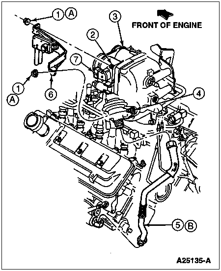
  1. Disconnect throttle linkage at throttle ball and automatic transmission linkage, if equipped, from throttle body (9E926). Remove two bolts securing bracket to upper intake manifold (9424) and position bracket with cables out of the way.


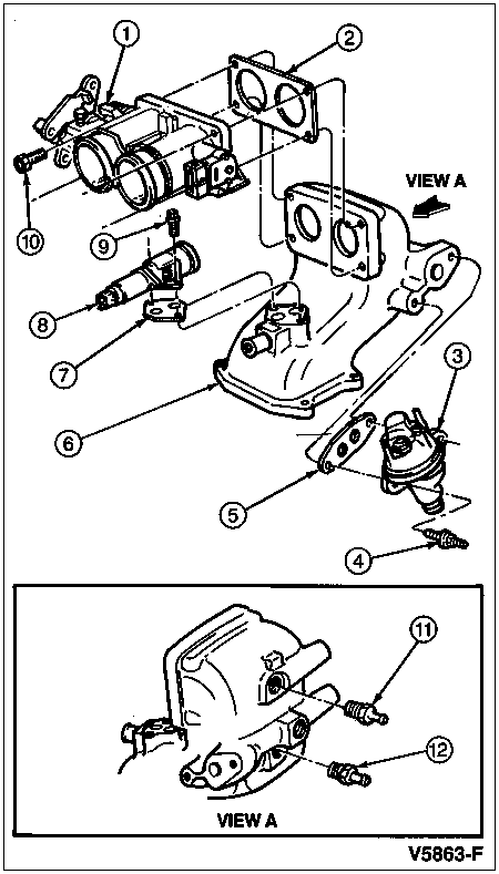
Throttle Body and Upper Intake Manifold Assembly


ItemPart NumberDescription
19E926Throttle Body
29E936Throttle Body Gasket
39F483EGR External Pressure Valve
4390715-S36Stud, 5/16-18 x 18 x 2.505 Hex Shoulder Pilot Stud
59D476EGR Valve Gasket
69424Intake Manifold
79F670Idle Air Control Gasket
89F715Idle Air Control Valve
9N605893-S8Bolt, M6 x 25mm Hex-Head UBS (2 Req'd)
10390774-S8Bolt, 5/16 x 1.5 Hex-Head UBS (6 Req'd)
11389642-S8Connector, 3/8 Hose x 3/8 External Pipe
12386153-S101Connector, 1/4 Hose x 3/8 External Pipe
  1. Disconnect electrical connectors at:

    1. idle air control valve (IAC valve) (9F715)
    1. throttle position sensor (TP sensor) (9B989)
    1. EGR valve sensor (9G428)
  1. Disconnect upper intake manifold vacuum fitting connections by disconnecting:

    1. vacuum line to MAP sensor
    1. vacuum line to EGR external pressure valve (9F483)
  1. Disconnect EGR and PCV systems by disconnecting:

    1. EGR valve flange nut
    1. PCV hose at rear of upper intake manifold
  1. Disconnect idle air control valve clean air supply hose, connected to idle air control valve port.


    EGR, 49-State Application
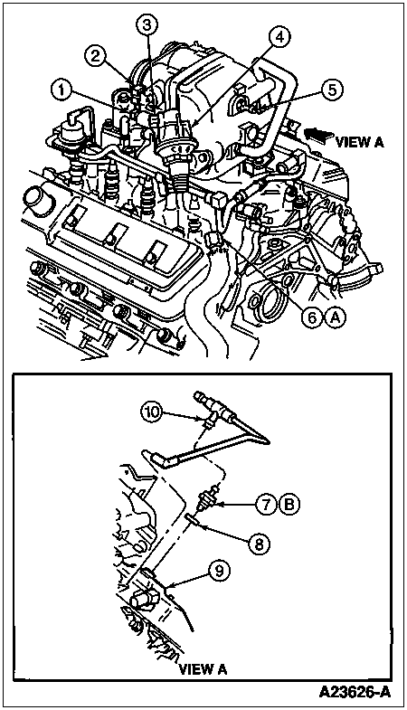


    ItemPart NumberDescription
    19F715Idle Air Control Valve
    29B989Throttle Position Sensor
    39G428EGR Valve Sensor
    49F483EGR External Pressure Valve
    5386153-S101Nipple for EGR Vacuum Supply Hose
    69D477EGR Valve to Exhaust Manifold Tube
    76A666Positive Crankcase Ventilation Valve
    86K780Positive Crankcase Ventilation Valve Gasket
    96582Valve Cover
    106C324Crankcase Vent Connector and Hose
    ATighten to 34-65 Nm
    (25-48 Lb-Ft)
    BTighten to 13-26 Nm
    (10-19 Lb-Ft)


    EGR, California Application


    ItemPart NumberDescription
    1Nut (Part of 9J433)
    2Stud (Part of 9E926)
    39E926Throttle Body
    4Stud (Part of 9F483)
    59D477EGR Tube Assembly
    69J433Transducer Assembly
    79B989Throttle Position Sensor
    ATighten to 13-16 Nm
    (10-12 Lb-Ft)
    BTighten to 34-65 Nm
    (25-48 Lb-Ft)
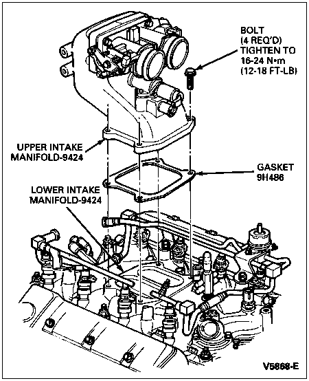
  1. Remove four upper intake manifold retaining bolts.

  1. Remove upper intake manifold and throttle body assembly.


Installation

  1. Clean and inspect the mounting faces of the lower and upper intake manifolds.

  1. Position new gasket on lower intake mounting face. The use of alignment studs may be helpful.

  1. Install upper intake manifold and throttle body to lower intake manifold, making sure gasket remains in place (if alignment studs are not used).

  1. Install four upper intake manifold retaining bolts. Tighten to 16-24 Nm (12-18 lb-ft).

  1. Install EGR valve to exhaust manifold tube (9D477).

  1. Connect PCV hose to rear of upper intake manifold.

  1. Connect vacuum lines to MAP sensor and EGR external pressure valve.

  1. Position throttle linkage bracket with cables to upper intake manifold. Install two attaching bolts and tighten to specification. Connect throttle cable and automatic transmission kickdown cable to throttle body.

  1. Connect electrical connectors at idle air control valve, throttle position sensor, and EGR valve sensor.

  1. Connect idle air control valve clean air supply hose.

  1. NOTE: When the battery (10655) has been disconnected and reconnected, some abnormal drive symptoms may occur while the powertrain control module (PCM) (12A650) relearns its adaptive strategy. The vehicle may need to be driven 16 km (10 miles) or more to relearn the strategy.

    Connect battery ground cable.

  1. Install air cleaner outlet tube.