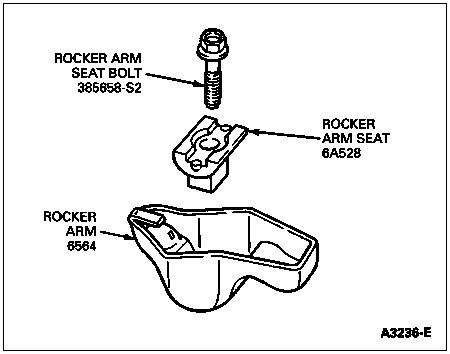
Remove rocker arm seat bolt, rocker arm seat (6A528) and rocker arm (6564).

Section 03-01C: Engine, 7.5L MFI | 1996 F-250, F-350, F-Super Duty Chassis Cab and Motorhome Workshop Manual |
Removal
Remove the valve cover (6582). Refer to Valve Cover and Gasket in the In-Vehicle Service portion of this section.
Remove rocker arm seat bolt, rocker arm seat (6A528) and rocker arm (6564).

Installation
Apply Ford Multi-Purpose Grease D0AZ-19584-AA or equivalent meeting Ford specification ESR-M1C159-A to the top of the intake and exhaust valve stems, the rocker arms and rocker arm seats.
NOTE: Make sure rocker arm seat is oriented in the rocker arm in original position.
Position the No. 1 piston (6108) at TDC at the end of the compression stroke (Position No. 1). Install the rocker arm, rocker arm seat, and rocker arm seat bolt on the following intake valves (6507) and exhaust valves (6505):
No. 1 intake valve No. 1 exhaust valve
No. 3 intake valve No. 8 exhaust valve
No. 7 intake valve No. 5 exhaust valve
No. 8 intake valve No. 4 exhaust valve
Make sure the rocker arm seat base is inserted into its slot on the cylinder head (6049) before tightening the rocker arm seat bolts. Tighten the rocker arm seat bolts to 25-34 Nm (18-25 lb-ft).
Position the crankshaft (6303) in Position No. 1 and install the rocker arm, rocker arm seat, and a rocker arm seat bolt on the following intake valves and exhaust valves:
No. 2 intake valve No. 2 exhaust valve
No. 4 intake valve No. 3 exhaust valve
No. 5 intake valve No. 6 exhaust valve
No. 6 intake valve No. 7 exhaust valve

Make sure the rocker arm seat base is inserted into its slot on the cylinder head before tightening the rocker arm seat bolts. Tighten the rocker arm seat bolts to 25-34 Nm (18-25 lb-ft). Adjust the valve clearance. Refer to Adjustments in this section.
Install valve cover and gasket. Refer to Valve Cover and Gasket in the In-Vehicle Service portion of this section.