Section 07-01: Transmission, Automatic, E4OD | 1997 F-250 Heavy Duty, F-350 and F-Super Duty Workshop Manual |
DISASSEMBLY
Disassembly/Reassembly of Subassemblies
Front and Rear Case Bushings
Disassembly and Assembly
NOTE: Inspect case bushing bores for nicks or burrs. Remove any minor nicks or burrs using a fine oil stone. Remove case bushings only if they show signs of excessive wear or scoring.
SPECIAL SERVICE TOOL(S) REQUIRED| Description | Tool Number |
|---|
| Impact Slide Hammer | T50T-100-A |
| Rear Case Bushing Replacer | T92T-77110-AH |
| Threaded Drawbar | T77F-1176-A |
 CAUTION: Be careful not to damage the case bore while removing the bushing.
NOTE: Remove and replace only one bushing at a time while using the other bushing in the case (7005) to help align the tool and bushing during installation. Always replace both bushings when either bushing is replaced.
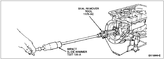
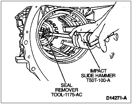
Remove the rear case bushing only using Seal Remover TOOL-1175-AC or equivalent and Impact Slide Hammer T50T-100-A as shown.
Rear Case Bushing Removal
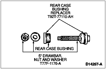
NOTE: The rear case bushing has one lube groove. The front case bushing has three lube grooves.
Using Rear Case Bushing Replacer T92T-77110-AH, place the rear case bushing on the portion of the tool as shown.
Place the remaining portion of Rear Case Bushing Replacer T92T-77110-AH and 127-mm (5-inch) Threaded Drawbar T77F-1176-A through the front of the case into the front case bushing as shown.
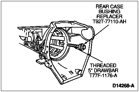
 CAUTION: Make sure the bushing and tool are centered in the bore.
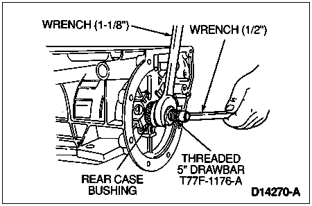
Place the portion of the tool with the rear case bushing into the rear of the case over the drawbar as shown. Attach washer and nut to drawbar and hand-tighten.
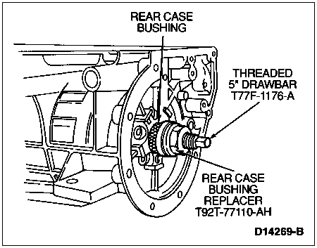
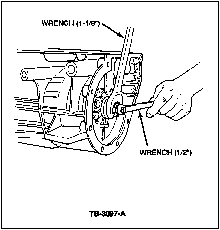
Hold the drawbar with a 1/2-inch wrench, while turning the nut with a 1-1/8-inch wrench as shown.
- Turn the nut until the rear case bushing is fully seated.
- Unscrew the nut and remove all tools.
Remove the front case bushing using Seal Remover TOOL-1175-AC or equivalent and Impact Slide Hammer T50T-100A as shown.
NOTE: The front case bushing has three lube grooves. The rear case bushing has one lube groove.
Using Rear Case Bushing Replacer T92T-77110-AH, place the front case bushing on the portion of tool as shown.
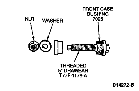
Set portion of tool with front case bushing and drawbar into bushing bore from the front as shown in the following illustration.
 CAUTION: Make sure the bushing and tool are centered in the bore.
Place the remaining portion of Rear Case Bushing Replacer T92T-77110-AH into the rear bushing in the case as a guide. Install washer and nut and hand-tighten.
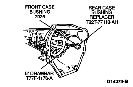
Hold the drawbar with a 1/2-inch wrench, while turning the nut with a 1-1/8-inch wrench as shown.
- Turn the nut until the front case bushing is fully seated.
- Unscrew the nut and remove all tools.
Main Control Valve Body
Thoroughly clean all parts, except non-metallic check balls, in clean solvent and blow dry with moisture-free compressed air.
Inspect all valve and plunger bores for scores. Check all fluid passages for obstructions. Inspect all mating surfaces for burrs and scores. If damaged, replace the main control valve body (7A100).
Inspect all springs for distortion. Check all valves and plungers for free movement in their respective bores when dry.
Roll the valves on a flat surface to check for bent condition.
Upper, Lower, Accumulator and Solenoid Bodies, Disassembled View
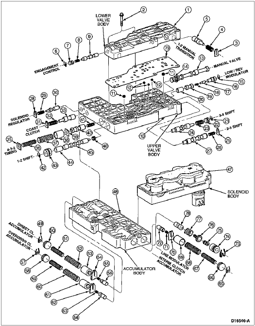
| Item | Part Number | Description |
|---|
| 1 | — | Body Control Valve — Lower |
| 2 | — | Bolt M1-1x36 Hex Flange Head (2 Req'd) |
| 3 | — | Plate, Spring Retaining |
| 4 | — | Spring, Shift Valve |
| 5 | — | Valve, Manual 1-2 Transmission |
| 6 | — | Retainer |
| 7 | — | Plug, Valve Retainer |
| 8 | — | Spring, Engagement Valve |
| 9 | — | Valve, Control Engagement |
| 10 | — | Body, Control Valve — Upper |
| 11 | — | Ball, 5/16-Inch Shuttle |
| 12 | — | Ball, 1/4-Inch Shuttle |
| 13 | — | Valve, Control Manual |
| 14 | — | Ring, Retaining |
| 15 | — | Retainer |
| 16 | — | Sleeve, Low/Reverse Modulator Valve |
| 17 | — | Plunger, Low/Reverse Modulator Valve |
| 18 | — | Spring, Low Servo Modulator |
| 19 | — | Valve, Low Servo Modulator |
| 20 | — | Valve, Low/Reverse Modulator |
| 21 | — | Retainer |
| 22 | — | Plug, Valve Retaining |
| 23 | — | Spring, Shift Valve |
| 24 | — | Valve, 3-4 Shift |
| 25 | — | Plate, Spring Retaining |
| 26 | — | Spring, 2-3 Shift Valve |
| 27 | — | Valve, 2-3 Shift |
| 28 | — | Plate, Spring Retaining |
| 29 | — | Spring Solenoid Regulator Valve |
| 30 | — | Solenoid, Regulator Valve |
| 31 | — | Plate, Spring Retaining |
| 32 | — | Spring, Shift Valve |
| 33 | — | Valve, Coast Clutch Shift |
| 35 | — | Plate, Spring Retaining |
| 36 | — | Spring, 4-3-2 Shift Timing |
| 37 | — | Spring, 4-3-2 Shift Timing |
| 38 | — | Plunger, Control Valve Shift Timing |
| 39 | — | Plate, Spring Retaining |
| 40 | — | Valve, 4-3-2 Timing |
| 41 | — | Spring, 4-3-2 Shift Timing |
| 42 | — | Retainer |
| 43 | — | Plug, Valve Retaining |
| 44 | — | Valve, 1-2 Shift |
| 45 | — | Valve, Drive 2 |
| 46 | — | Spring, 1-2 Shift Valve |
| 47 | 7G391 | Solenoid Body Assy |
| 48 | 7G422 | Accumulator Valve Body Control |
| 49 | — | Retainer |
| 50 | — | Plug, Valve Retainer |
| 51 | — | Spring, Accumulator Valve — Inner |
| 52 | — | Spring, Accumulator Valve — Outer |
| 53 | — | Plunger, Accumulator Regulator |
| 54 | — | Retainer, Accumulator Spring |
| 55 | — | Spring, Accumulator Regulator Valve |
| 56 | — | Valve, Accumulator Regulator |
| 57 | — | Retainer |
| 58 | — | Plug, Valve Retaining |
| 59 | — | Spring, Accumulator Valve — Inner |
| 60 | — | Spring, Accumulator Valve — Outer |
| 61 | — | Plunger, Accumulator Regulator |
| 62 | — | Retainer, Accumulator Spring |
| 63 | — | Spring, Accumulator Regulator Valve |
| 64 | — | Valve, Accumulator Regulator |
| 65 | — | Retainer |
| 66 | — | Plug, Valve Retaining |
| 67 | — | Spring, Accumulator Valve — Inner |
| 68 | — | Spring, Accumulator Valve — Outer |
| 69 | — | Plunger, Accumulator Regulator |
| 70 | — | Retainer, Accumulator Spring |
| 71 | — | Spring, Accumulator Regulator Valve |
| 72 | — | Valve, Accumulator Regulator |
| 73 | — | Retainer |
| 74 | — | Sleeve, Line Press Modulator |
| 75 | — | Plunger, Line Press Modulator |
| 76 | — | Spring and Retainer Assy, Press Modulator |
| 77 | — | Spring, Throttle Press Line Modulator |
| 78 | — | Valve, Line Press Modulator |
| 79 | 7A008 | Control Valve Body Separator Plate |
Pump Assembly
SPECIAL SERVICE TOOL(S) REQUIRED| Description | Tool Number |
|---|
| Impact Slide Hammer | T59L-100-B |
| Front Pump Seal Replacer | T63L-77837-A |
Pump Assembly, Disassembled View
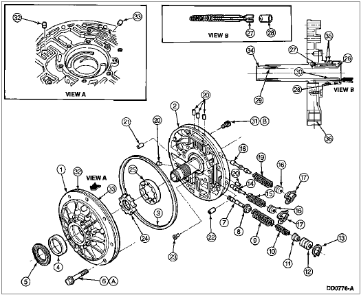
| Item | Part Number | Description |
|---|
| 1 | — | Pump Body (Part of 7A103) |
| 2 | — | Control Body (Part of 7A103) |
| 3 | 7A248 | Square-Cut Front Pump Seal |
| 4 | 7B258 | Converter Hub Bushing |
| 5 | 7A248 | Front Pump Seal |
| 6 | N805260-S | Bolt and Washer Assy
(9 Req'd) |
| 7 | — | Main Regulator Valve
(Part of 7A103) |
| 8 | — | Spring Retainer
(Part of 7A103) |
| 9 | — | Outer Spring (Part of 7A103) |
| 10 | — | Inner Spring (Part of 7A103) |
| 11 | — | Main Regulator Booster Valve (Part of 7A103) |
| 12 | — | Main Regulator Booster Sleeve (Part of 7A103) |
| 13 | — | Retainer Clip
(Part of 7A103) |
| 14 | — | Converter Regulator Valve (Part of 7A103) |
| 15 | — | Spring (Part of 7A103) |
| 16 | — | End Plug (Part of 7A103) |
| 17 | — | Retainer Clip (Part of 7A103) |
| 18 | — | Converter Clutch Control Valve (Part of 7A103) |
| 19 | — | Spring (Part of 7A103) |
| 20 | — | Solid Cup Plug
(Part of 7A103) |
| 21 | — | Orificed Cup Plug
(Part of 7A103) |
| 22 | — | Orificed Cup Plug
(Part of 7A103) |
| 23 | — | Air Bleed Check Valve Assy (Part of 7A103) |
| 24 | — | Inner Gerotor Gear
(Part of 7A103) |
| 25 | — | Outer Gerotor Gear
(Part of 7A103) |
| 26 | N805802 | Orifice Cup Plug |
| 27 | — | Spring and Stop Assy
(Part of 7H132) |
| 28 | — | Solid Cup Plug
(Part of 7A103) |
| 29 | — | Front Input Shaft Bushing (Part of 7A103) |
| 30 | — | Rear Input Shaft Bushing (Part of 7A103) |
| 31 | — | Bolt, M8 (11 Req'd)
(Part of 7A103) |
| 32 | — | Orificed Cup Plug
(Part of 7A103) |
| 33 | — | Orificed Cup Plug
(Part of 7A103) |
| 34 | 7L323 | Front Pump Stator Support Seal |
| 35 | 7G402 | Coast Clutch Seal |
| 36 | — | Inlet Tube Bore
(Part of 7A103) |
| A | — | Tighten to 24-31 Nm
(18-23 Lb-Ft) |
| B | — | Tighten to 24-31 Nm
(18-23 Lb-Ft) |
Disassembly
Inspect front pump seal. If damaged, remove with Impact Slide Hammer T59L-100-B and Seal Remover TOOL-1175-AC or equivalent.
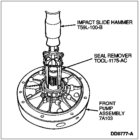
Remove front pump stator support seal from front of stator support.
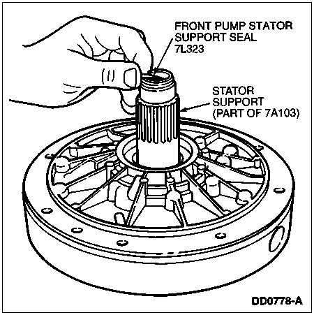
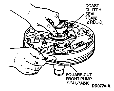
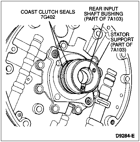
Remove two Teflon® coast clutch seals from stator support. Remove pump outer diameter square-cut front pump seal.
 CAUTION: Do not reuse orifice cup plug or spring and stop assembly. Make sure the old rubber stop is removed (it can become separated from the spring assembly).
 CAUTION: Use care not to damage any machined surfaces of stator support.
Remove and discard orifice cup plug and spring and stop assembly.
Clean and inspect bore, making sure bore is clean of any debris.

| Item | Part Number | Description |
|---|
| 1 | — | Stator Support Mating Surface |
| 2 | N805802 | Orifice Cup Plug
(Serviced in 7H132) |
| 3 | 7E486 | No. 2A Overdrive Sun Gear Thrust Bearing |
| 4 | — | Inlet Tube Bore |
| 5 | 7H132 | Spring and Stop Assy (Serviced in 7H132) |
| 6 | — | Front Input Shaft Bushing (Part of 7A103) |
| 7 | — | Rear Input Shaft Bushing (Part of 7A103) |
| 8 | N805802 | Orifice Cup Plug |
| 9 | 7H132 | Converter Drainback Spring and Stop Assy |
Obtain Banding Tool D89L-7700-A or equivalent and one 10 mm bolt prior to removing pump body bolts. This tool is needed to align the pump with the control body assembly during reassembly.
NOTE: For the next two steps, refer to Pump Assembly, disassembled view.
Remove ten bolts. Support pump body. Remove the remaining bolt. Separate pump control body from pump body.
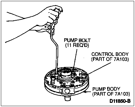
 CAUTION: DO NOT remove any of the remaining cup plugs unless directed to do so in other steps. DO NOT remove stator support from control body as this can distort the surface of the control body.
Apply pressure to main regulator booster sleeve and remove retainer. Remove main regulator valve assembly.
Remove converter regulator valve assembly by applying pressure to end plug and removing retainer clip with small screwdriver or tweezers.
Remove converter clutch shift valve assembly by applying pressure to end plug and removing retainer clip with small screwdriver or tweezers.
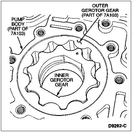
Remove gerotor gearset from pump body.
Clean all pump parts in solvent and dry with compressed air.
Inspect pump gears, faces, gear teeth, pump housing and mating surfaces for damage or scoring. Replace entire pump if any part is damaged or worn.
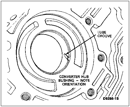
Inspect converter hub bushing. Replace entire pump if scored or excessively worn.
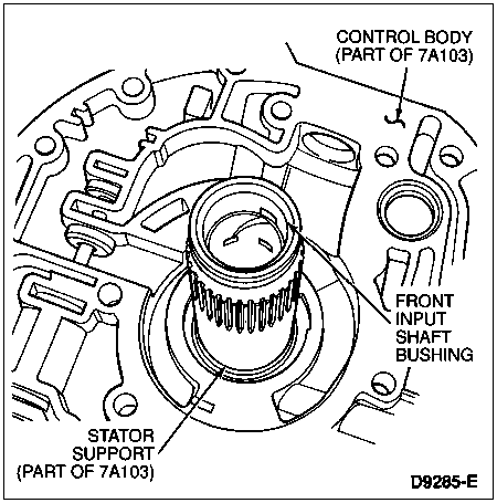
Inspect input shaft bushings. If bushings are worn or scored, replace entire pump assembly.
Place pump gerotor gearset in pump gear pocket, centered to pump bushing diameter.
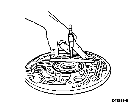
Using depth micrometer, measure and record the depth of inner gerotor gear face to the machined surface of the pump body. Center the inner diameter of the inner gear over the bushing for this step.
Repeat measurement for a total of three readings in equally spaced locations on gear face.
Remove the inner gear and install the outer gear.

Using depth micrometer, measure and record the depth of the outer gerotor gear to the machined surface of the pump body.
All depth measurements must be within 0.0381-0.0559 mm (0.0015-0.0022 inch). If either reading is out of specification, replace the front pump assembly.
Inspect all valve and plug bores for scoring or damage. Check all passages for obstructions. Inspect mating surfaces for burrs and scoring.
Inspect all springs for distortion. When dry, make sure all valves and plugs move freely within their bores.
Assembly
Install main regulator valve assembly as shown in pump assembly, disassembled view. Apply pressure to main regulator booster sleeve and install retainer clip. Make sure retainer clip is properly seated.
Install converter clutch shift valve assembly.
Install torque converter regulator valve assembly.
Lightly coat the gerotor gears with transmission fluid and install in pump housing. The dot on the inner gerotor gear must face the control body assembly.

 CAUTION: Prior to pump assembly, make sure all cup plugs are installed.
 CAUTION: Inspect mating surfaces of pump body and control body to make sure they are clean and free of nicks and burrs.
Lower the control body and stator assembly onto the pump body, aligning the 28-mm round hole in the control body with the 28-mm hole in the pump body.
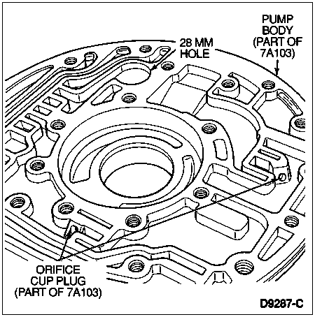
Loosely install eleven M8x50 bolts. Install one 10-mm alignment bolt in the position shown and install Banding Tool D89L-77000-A or equivalent with clamp by filter inlet. Align outer bolt holes and tighten banding tool.
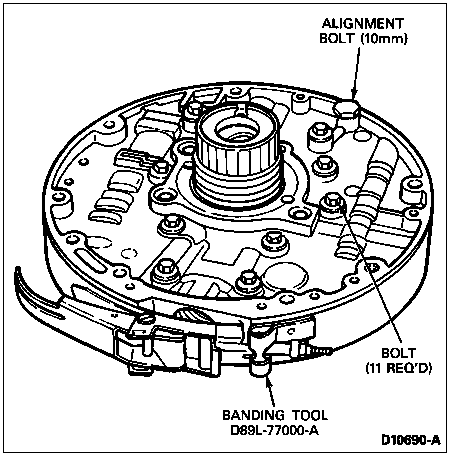
Tighten bolts to 24-31 Nm (18-23 lb-ft). Remove banding tool and 10-mm alignment bolt. Make sure the outer edges of the control body and the pump body are completely aligned.
NOTE: Make sure seal grooves are clean and free of burrs.
NOTE: Make sure coast clutch seals are fully seated in grooves and oriented 180 degrees apart.
Install coast clutch Teflon® seals. Install outer diameter seal.
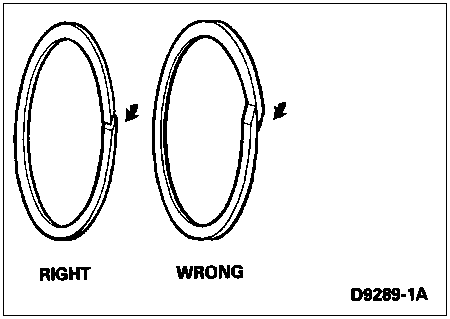

Install front pump stator support seal on front of stator support in same manner as coast clutch seals.
NOTE: Insert the end with the rubber stop into the bore first.
Install a new spring and stop assembly from service kit E9TZ-7H132-B.

| Item | Part Number | Description |
|---|
| 1 | — | Stator Support Mating Surface |
| 2 | N805802 | Orifice Cup Plug
(Serviced in 7H132) |
| 3 | 7E486 | No. 2A Overdrive Sun Gear Thrust Bearing |
| 4 | — | Inlet Tube Bore |
| 5 | 7H132 | Spring and Stop Assy (Serviced in 7H132) |
| 6 | — | Front Input Shaft Bushing
(Part of 7A103) |
| 7 | — | Rear Input Shaft Bushing
(Part of 7A103) |
| 8 | N805802 | Orifice Cup Plug |
| 9 | 7H132 | Converter Drainback Spring and Stop Assy |
NOTE: Make sure the edge of the cup plug is seated just below the stator support surface that mates with the No. 2 needle bearing assembly.
Using a small drift and mallet, install a new cup plug from the service kit E9TZ-7H132-B.
Using Front Pump Seal Replacer T63L-77837-A, install front pump seal if removed.
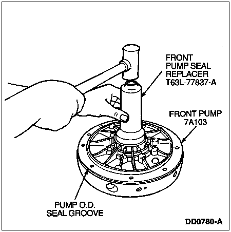
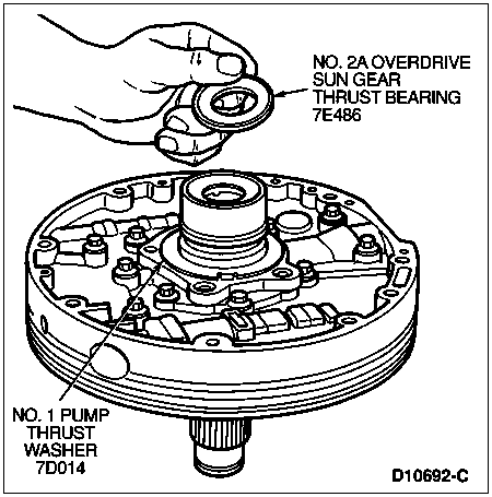
Install No. 1 pump thrust washer and No. 2A overdrive sun gear thrust bearing into pump stator support. Use a light film of petroleum jelly to hold washer and bearing assembly in place.
Coast Clutch Assembly
SPECIAL SERVICE TOOL(S) REQUIRED| Description | Tool Number |
|---|
| Clutch Spring Compressor | T65L-77515-A |
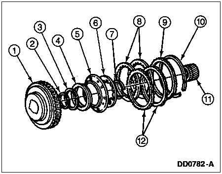
Refer to the following disassembled view of the coast clutch assembly for component location and orientation.
Coast Clutch Assembly, Disassembled View
| Item | Part Number | Description |
| 1 | 7G387 | Coast Clutch Cylinder |
| 2 | 7A548 | Coast Clutch Piston Inner Seal |
| 3 | 7A548 | Coast Clutch Piston Outer Seal |
| 4 | 7A262 | Coast Clutch Piston |
| 5 | 7N519 | Apply Ring |
| 6 | 7B070 | Coast Clutch Piston Spring |
| 7 | 7A527 | Retaining Ring |
| 8 | 7B164 | Coast Clutch Friction Plates |
| 9 | 7B066 | Coast Clutch Pressure Plate |
| 10 | 7D483 | Coast Clutch Pressure Plate Retainer Snap Ring |
| 11 | 7D063 | Overdrive Sun Gear |
| 12 | 7B442 | Coast Clutch Steel Plates |
Disassembly
Remove overdrive sun gear (7D063) from coast clutch cylinder.

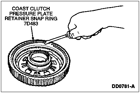
Remove selective coast clutch pressure plate retainer snap ring.
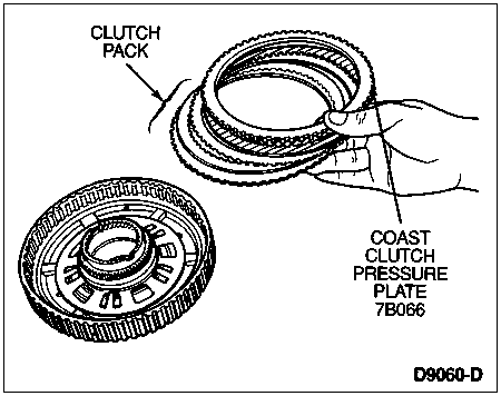
Remove coast clutch pressure plate and clutch plates from coast clutch cylinder. Tag clutch pack for reassembly.
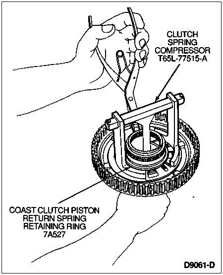
 CAUTION: Do not fully compress the return springs.
Using Clutch Spring Compressor T65L-77515-A, compress coast clutch piston return spring and remove coast clutch piston return spring retaining ring. Remove compressor tool. Discard coast clutch return spring retaining ring.
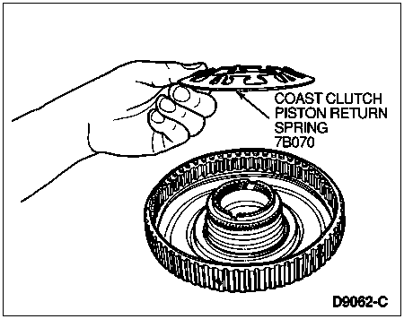
Remove coast clutch piston return spring.
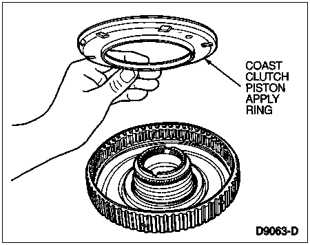
Remove coast clutch piston apply ring.
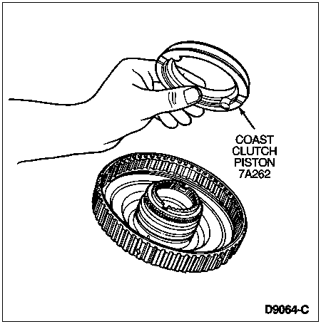
Remove coast clutch piston from coast clutch cylinder.
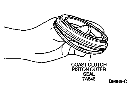
Remove coast clutch piston outer seal from coast clutch piston.
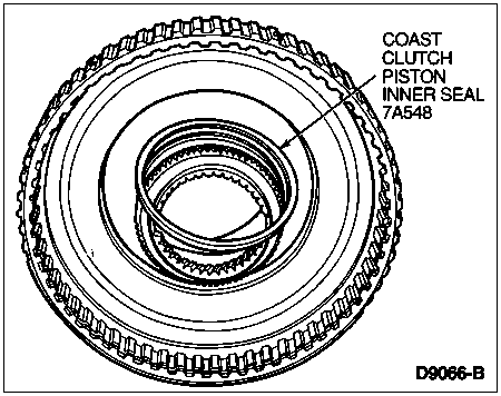
Remove coast clutch piston inner seal from coast clutch cylinder.
Assembly
NOTE: Soak all friction plates for 15 minutes in clean Motorcraft MERCON® Multi-Purpose Automatic Transmission Fluid XT-2-QDX or MERCON® equivalent.
Lightly lube all O-ring seals before installing, using Motorcraft MERCON® Multi-Purpose Automatic Transmission Fluid XT-2-QDX or MERCON® equivalent.
Install coast clutch piston inner seal so that lip is facing toward bottom (downward) into coast clutch cylinder.

Install coast clutch piston outer seal so that lip is facing toward bottom (downward) onto coast clutch piston.

Install coast clutch piston into coast clutch cylinder.

Install coast clutch piston apply ring.

Install coast clutch piston return spring.

 CAUTION: Do not fully compress the return springs.
Using Clutch Spring Compressor T65L-77515-A, compress coast clutch piston return spring and install coast clutch piston return spring retaining ring.

Install clutch plates alternately, starting with steel plate and ending with coast clutch pressure plate.

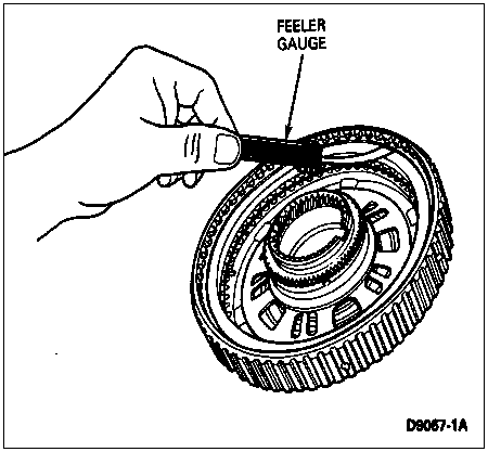
Install coast clutch pressure plate retainer snap ring. Check stack-up clearance in three places, 120° apart, using feeler gauge. If clearance is not 1.27-0.76 mm (0.030-0.050 inch), install correct coast clutch pressure plate retainer snap ring and recheck clearance. Refer to the Specifications portion of this section for selective snap ring thicknesses and part numbers.
Install overdrive sun gear with short end of gear downward into coast clutch cylinder.

Overdrive Ring Gear and Center Shaft Assembly
Refer to the following disassembled view of the overdrive ring gear and center shaft for component location and orientation.
Overdrive Ring Gear and Center Shaft Assembly, Disassembled View
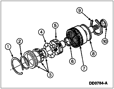
| Item | Part Number | Description |
|---|
| 1 | 7G375 | Retaining Ring — Flat |
| 2 | 377135-S | Retaining Ring — Small |
| 3 | 7A089 | Overdrive One-Way Clutch Assy |
| 4 | 7L339 | No. 3 Overdrive Overrunning Clutch Thrust Washer |
| 5 | 7B446 | Overdrive Planet Assy |
| 6 | 7F240 | No. 4 Overdrive Planet Thrust Bearing Assy |
| 7 | 7A153 | Overdrive Ring Gear |
| 8 | 7A658 | Overdrive Center Shaft |
| 9 | 7G375 | Wavy Retaining Ring |
| 10 | 7G178 | No. 5 Overdrive Center Shaft Thrust Bearing Assy |
Disassembly
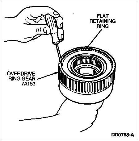
Remove flat retaining ring.
Remove overdrive one-way clutch with inner and outer races.
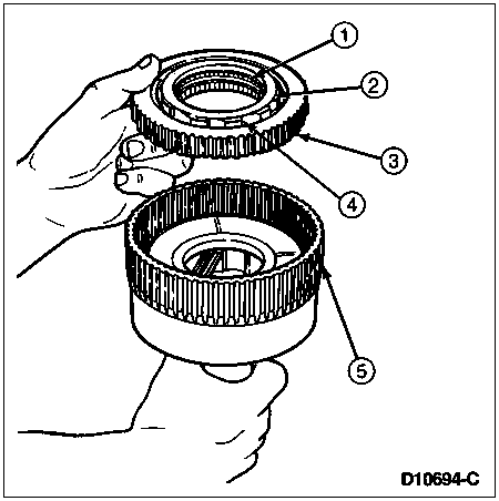
| Item | Part Number | Description |
|---|
| 1 | — | Inner Race (Part of 7A089) |
| 2 | 377135-S | Small Retaining Ring |
| 3 | — | Outer Race (Part of 7A089) |
| 4 | — | One-Way Clutch
(Part of 7A089) |
| 5 | 7A153 | Overdrive Ring Gear |
Remove No. 3 overdrive overrunning clutch thrust washer from front of overdrive planet assembly.
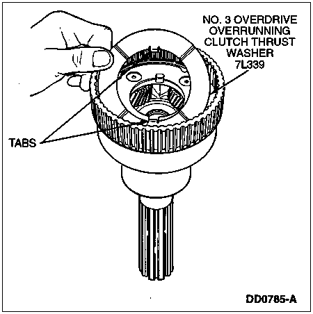
NOTE: The No. 4 overdrive planet thrust bearing may stay in the ring gear.
Remove overdrive planet assembly.
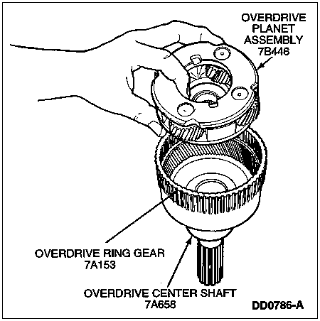
Remove wavy retaining ring.
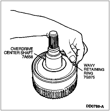
Remove overdrive center shaft (7A658) from overdrive ring gear.
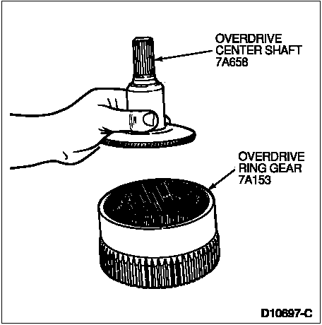
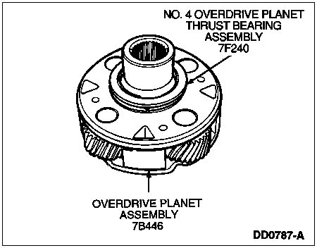
 CAUTION: Use care not to damage No. 4 overdrive planet thrust bearing assembly.
Remove No. 4 overdrive planet thrust bearing assembly from rear face of overdrive planet assembly.
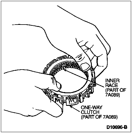
Push out one-way clutch and inner race.
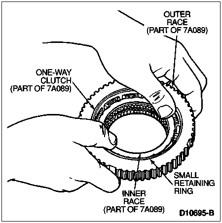
Remove inner race from one-way clutch.
Assembly
Install overdrive center shaft into overdrive ring gear.
Secure overdrive center shaft to overdrive ring gear with wavy retaining ring.

Install No. 4 overdrive planet thrust bearing assembly with outer lip downward on rear face of overdrive planet assembly.
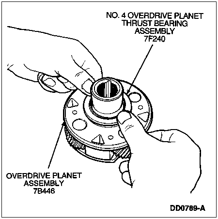
 CAUTION: The input shaft (7017) and overdrive planet assembly are serviced as mating components.
NOTE: Different vehicle applications will have different planet assemblies. Refer to master parts catalog for correct usage.
Install overdrive planet assembly into overdrive center shaft and overdrive ring gear assembly.

Install No. 3 overdrive overrunning clutch thrust washer on front of overdrive planet assembly.

Install retaining ring and unitized plastic cage into outer race.
NOTE: When installed, inner race must rotate counterclockwise.
Install inner race into one-way clutch assembly with undercut facing small retaining ring.
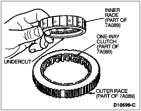
Install overdrive one-way clutch into overdrive ring gear with small retaining ring facing upwards.

| Item | Part Number | Description |
|---|
| 1 | — | Inner Race (Part of 7A089) |
| 2 | 377135-S | Small Retaining Ring |
| 3 | — | Outer Race (Part of 7A089) |
| 4 | — | One-Way Clutch
(Part of 7A089) |
| 5 | 7A153 | Overdrive Ring Gear |
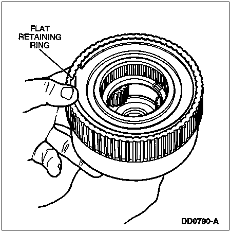
Install flat retaining ring.
NOTE: Inner bearing race lip must face upward.
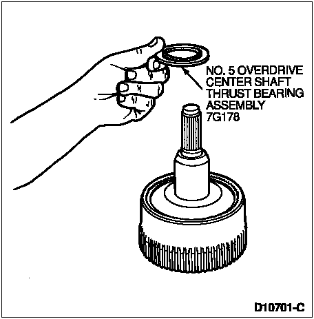
NOTE: Lightly lubricate thrust bearing with petroleum jelly to hold it in place during assembly.
Install No. 5 overdrive center shaft thrust bearing assembly onto overdrive center shaft.
Remove selective coast clutch pressure plate retainer snap ring, coast clutch pressure plate and clutch plates from coast clutch cylinder.
For ease of assembly, install overdrive center shaft assembly into coast clutch cylinder
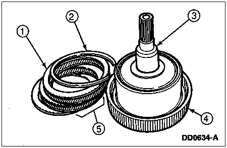
| Item | Part Number | Description |
|---|
| 1 | 7B066 | Coast Clutch Pressure Plate |
| 2 | 7D483 | Coast Clutch Pressure Plate Retainer Snap Ring |
| 3 | — | Overdrive Center Shaft Assy |
| 4 | 7G387 | Coast Clutch Cylinder |
| 5 | — | Clutch Pack |
Reinstall clutch plates, coast clutch pressure plate and selective coast clutch pressure plate retainer snap ring into coast clutch cylinder.
Intermediate/Overdrive Cylinder Assembly
SPECIAL SERVICE TOOL(S) REQUIRED| Description | Tool Number |
|---|
Clutch Spring Compressor Plate
(Part of T89T-70010-C) | T89T-70010-C2 |
Clutch Spring Compressor Bar
(Part of T88C-77000-AH) | T88C-77000-AH2 |
| Clutch Spring Compressor Plate | T89T-70010-F |
| O-Ring Tool | T71P-19703-C |
Refer to the following disassembled view of the intermediate/overdrive cylinder assembly for component location and orientation.
Intermediate/Overdrive Cylinder Assembly, Disassembled View
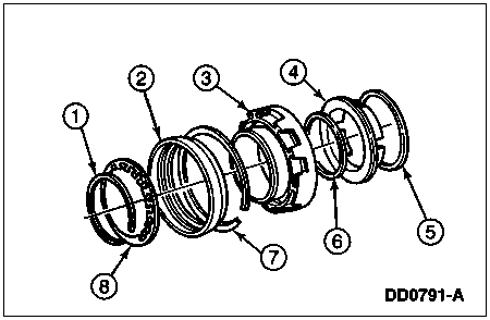
| Item | Part Number | Description |
|---|
| 1 | 7A527 | Overdrive Clutch Piston Return Spring Retainer |
| 2 | 7A262 | Overdrive Clutch Piston and (Bonded) Seal Assy |
| 3 | 7G384 | Intermediate/Overdrive Cylinder |
| 4 | 7E005 | Intermediate Clutch Piston |
| 5 | 7F224 | Intermediate Clutch Piston Outer Seal |
| 6 | 7F225 | Intermediate Clutch Piston Inner Seal |
| 7 | 7D483 | Intermediate Cylinder Retaining Ring |
| 8 | 7B070 | Overdrive Clutch Piston Return Spring |
Disassembly
Using Clutch Spring Compressor Plate T89T-70010-C2 (Part of T89T-70010-C), Clutch Spring Compressor Bar T88C-77000-AH2 (Part of T88C-77000-AH) and Clutch Spring Compressor Plate T89T-70010-F, compress the overdrive clutch piston return spring.
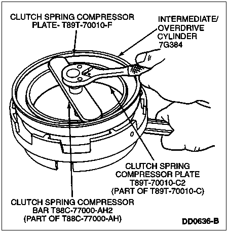
Remove overdrive clutch piston return spring retainer.
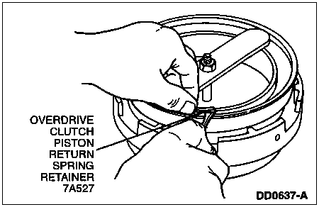
Remove compressor tool assembly.
Remove overdrive clutch piston return spring.

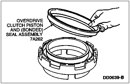
NOTE: Overdrive piston seals are bonded to the piston. If the seals are damaged, replace the piston assembly.
Remove overdrive clutch piston and (bonded) seal assembly.
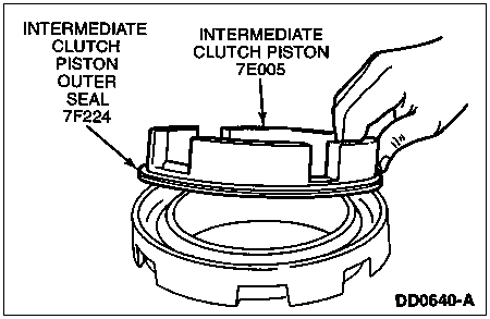
Remove intermediate clutch piston (7E005).
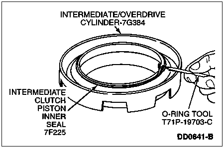
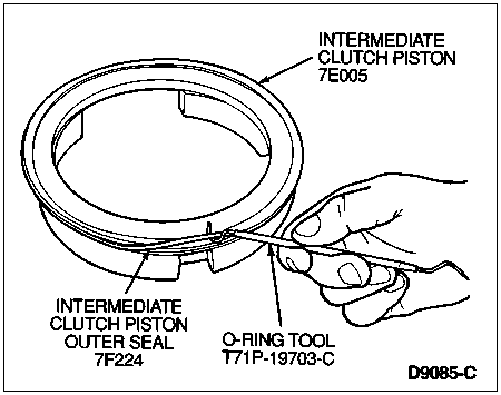
Remove intermediate clutch piston inner seal (7F225) from cylinder bore, using O-Ring Tool T71P-19703-C.
Remove intermediate clutch piston outer seal (7F224) from intermediate clutch piston.
Assembly
NOTE: Prior to reassembly, inspect check ball, cup plugs and feedbolt threads for contamination or damage. Clean or replace as necessary.
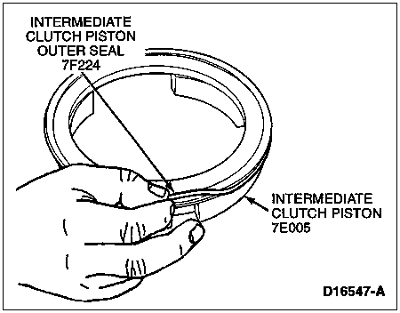
Install intermediate clutch piston outer seal onto intermediate clutch piston with lip seal facing upward.
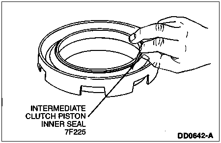
Install intermediate clutch piston inner seal into cylinder bore with lip seal facing downward toward cylinder.
NOTE: Piston should rotate freely in cylinder.
Install intermediate clutch piston.

 CAUTION: Overdrive piston lip seals are bonded to the piston. Use care not to damage or roll lip seal over.
 CAUTION: If seals are damaged, the entire piston and seal assembly must be replaced.
NOTE: Coat inner and outer bonded lip seals with petroleum jelly.
NOTE: Piston should rotate freely in cylinder.
Position overdrive clutch piston onto intermediate/overdrive cylinder at a slight angle. Then, rotate piston while pressing it down until fully sealed onto cylinder.

NOTE: Overdrive clutch piston return spring must be installed with fingers facing upward.
Install overdrive clutch piston return spring.

Using Clutch Spring Compressor Plate T89T-70010-F, Clutch Spring Compressor Bar T88C-77000-AH2 and Clutch Spring Pressure Plate T89T-70010-C2, compress return spring.

Install overdrive clutch piston return spring retainer. Make sure retainer is fully seated.

Remove tool assembly.
Center Support
Disassembly
Remove two direct clutch seal rings and No. 6 center support thrust washer (7L326).
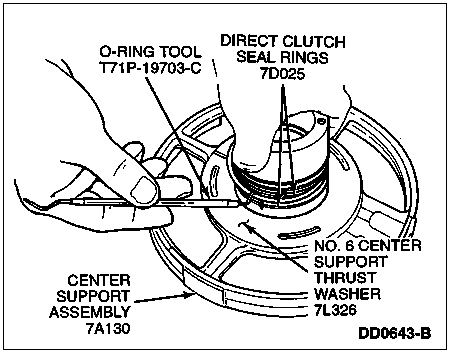
Inspect No. 6 center support thrust washer, center support seal ring grooves, hub inner and outer diameters and feedbolt threads for contamination or damage. Clean or replace as necessary.
Inspect ball bearing inside center support for damage. Service as required.
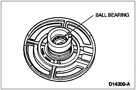
Assembly
Install No. 6 center support thrust washer using a light film of petroleum jelly to hold in place.
Install two new direct clutch seal rings.
Intermediate Band Assembly and Intermediate Brake Band Servo Assembly
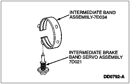
- Inspect intermediate band assembly friction material. Service as required.
- Inspect intermediate brake band servo assembly piston seal. If damaged, replace entire servo assembly.
Forward Hub and Ring Gear
Disassembly
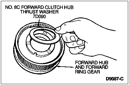
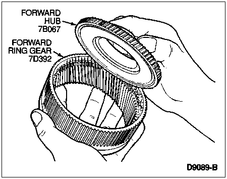
Remove No. 8C forward clutch hub thrust washer from front face of hub.
Remove forward hub retaining ring using screwdriver.
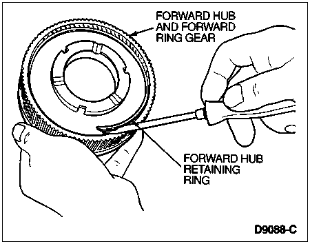
Remove forward hub from forward ring gear.
Assembly
Install forward hub into forward ring gear.

NOTE: Make sure forward hub retaining ring is fully seated in ring groove.
Install forward hub retaining ring.

NOTE: Lightly lubricate thrust washer with petroleum jelly to hold it in place during assembly.
Install No. 8C forward clutch hub thrust washer on the hub.
Direct Clutch Assembly and Intermediate Brake Drum
SPECIAL SERVICE TOOL(S) REQUIRED| Description | Tool Number |
|---|
| Clutch Spring Compressor | T65L-77515-A |
| O-Ring Tool | T71P-19703-C |
Refer to the following disassembled view of the direct clutch and intermediate brake drum for component location and orientation.
Direct Clutch Assembly and Intermediate Brake Drum, Disassembled View
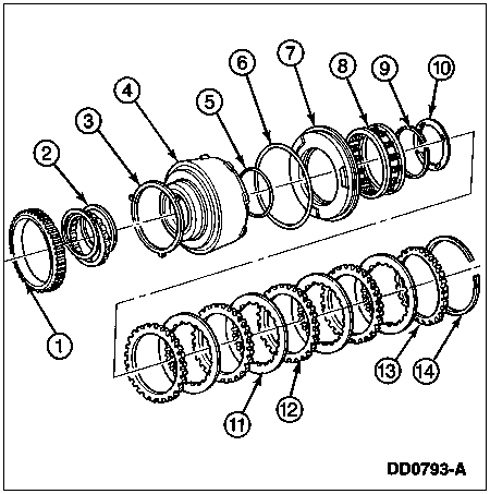
| Item | Part Number | Description |
|---|
| 1 | — | Intermediate One-Way Clutch Outer Race (Part of 7A089) |
| 2 | — | Intermediate One-Way Clutch (Part of 7A089) |
| 3 | 7G401 | Intermediate One-Way Clutch Thrust Washer (No. 7) |
| 4 | 7D044 | Intermediate Brake Drum |
| 5 | 7A548 | Direct Clutch Piston Inner Seal |
| 6 | 7A548 | Direct Clutch Piston Outer Seal |
| 7 | 7A262 | Direct Clutch Piston |
| 8 | 7F235 | Direct Clutch Return Spring Assy |
| 9 | 7C122 | Direct Clutch Return Spring Retaining Ring |
| 10 | 7C096 | Intermediate Brake Drum Thrust Washer (No. 8A) |
| 11 | 7B164 | Direct Clutch Internal Spline Plates — Friction |
| 12 | 7B442 | Direct Clutch External Spline Plates — Steel |
| 13 | 7B066 | Direct Clutch Pressure Plate |
| 14 | 377126-S | Direct Clutch Pressure Plate Retaining Ring (Selective) |
Disassembly
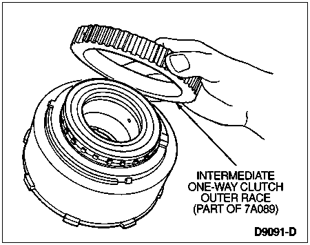
Remove intermediate one-way clutch outer race.
Remove top end cap and intermediate one-way clutch.
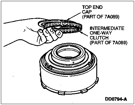
Remove bottom end cap.
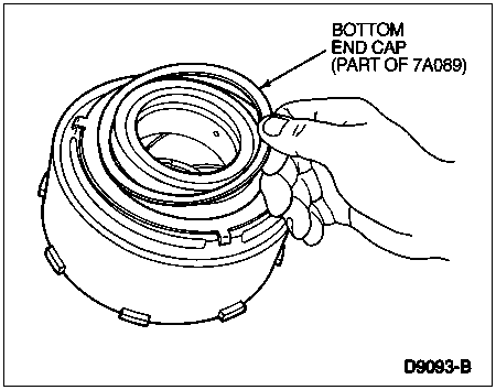
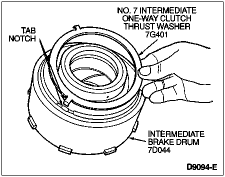
Remove No. 7 intermediate one-way clutch thrust washer from rear face of intermediate brake drum.
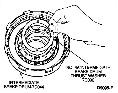
Remove No. 8A intermediate brake drum thrust washer from front face of intermediate brake drum.
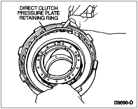
Remove direct clutch pressure plate retaining ring using screwdriver.
Remove direct clutch pressure plate and clutch pack. Tag for reassembly.
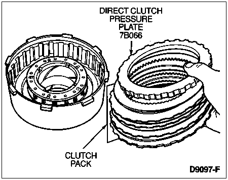
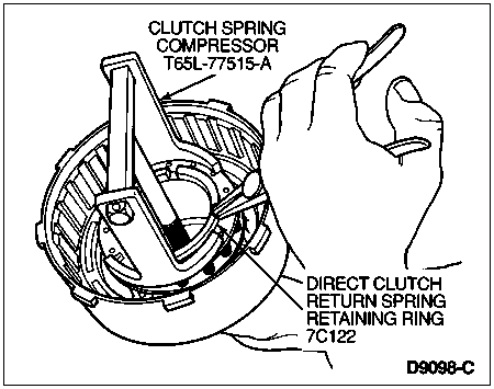
 CAUTION: Do not fully compress the return springs.
Using Clutch Spring Compressor T65L-77515-A, compress direct clutch return spring assembly and remove direct clutch return spring retaining ring. Remove compressor tool.
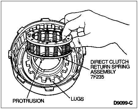
Remove direct clutch return spring assembly.
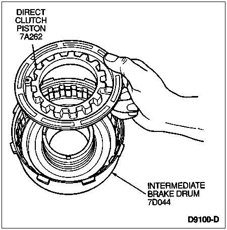
Remove direct clutch piston from intermediate brake drum.
Remove inner and outer direct clutch piston seals from intermediate brake drum using O-Ring Tool T71P-19703-C.
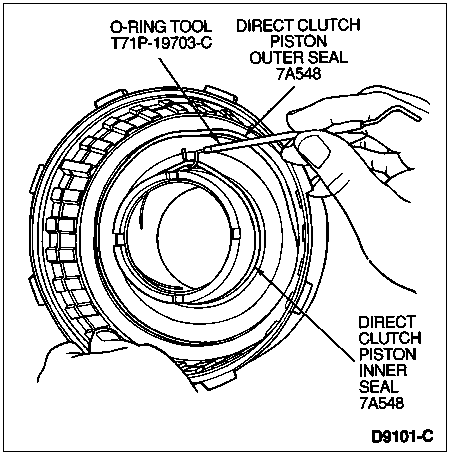
Assembly
Install direct clutch piston inner seal into intermediate brake drum with seal lip facing downward.
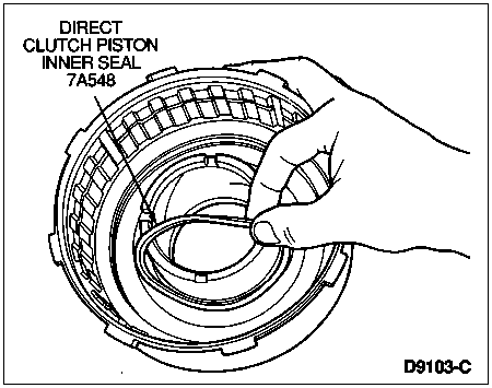
Install direct clutch piston outer seal into intermediate brake drum with seal lip facing downward.
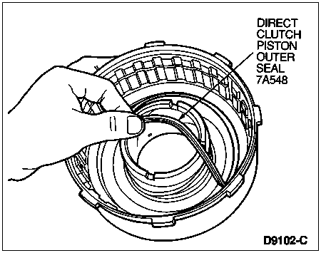
Inspect direct clutch piston check ball for freedom of movement and proper seating. Clean with solvent if necessary. Replace direct clutch piston if damaged.
NOTE: Piston should rotate freely in drum.
Install direct clutch piston into intermediate brake drum.

NOTE: Make sure protrusions on spring retainer are properly engaged with lugs on direct clutch piston.
Install direct clutch return spring assembly.

 CAUTION: Do not fully compress the return springs.
Compress direct clutch return spring assembly using Clutch Spring Compressor T65L-77515-A. Install direct clutch return spring retaining ring, then remove compressor tool.

 CAUTION: Mixing or using friction plates without lube grooves will cause shift concerns and can cause damage.
NOTE: The direct clutch friction plates have lube grooves in the friction material.
NOTE: Soak the clutch plates with clean Motorcraft MERCON® Multi-Purpose Automatic Transmission Fluid XT-2-QDX or MERCON® equivalent for fifteen minutes.
Install three, four or five plate clutch pack (depending on model), starting with steel plate and alternating with friction plates. Install direct clutch pressure plate.

Install selective retaining ring. Check stack-up in three positions 120 degrees apart using feeler gauge. If clearance is not 2.06-1.14 mm (0.081-0.045 inch), install correct selective retaining ring and recheck clearance. Refer to the Specifications portion of this section for selective snap ring thicknesses and part numbers.

Install No. 7 intermediate one-way clutch large thrust washer on face of intermediate brake drum.

NOTE: Top and bottom end caps are identical.
Install bottom end cap.
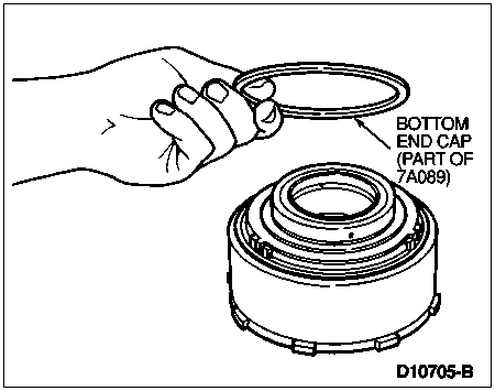
NOTE: Lip on the intermediate one-way clutch must face upward.
Install intermediate one-way clutch. Install top end cap.

NOTE: Shoulder on intermediate one-way clutch outer race must face upward.
Install intermediate one-way clutch outer race and check that it turns counterclockwise.
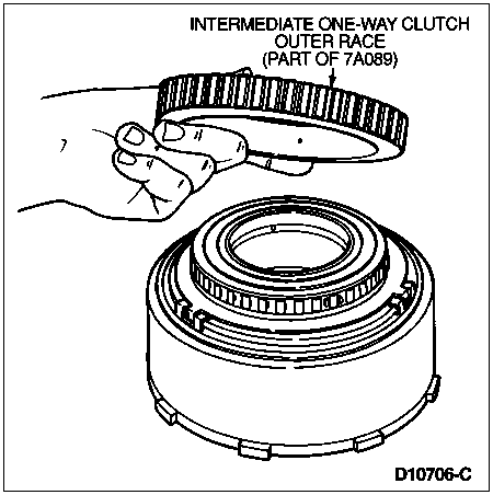
NOTE: Lightly lubricate thrust washer with petroleum jelly to hold it in place during assembly.
Install No. 8A intermediate brake drum thrust washer on face of intermediate brake drum.

Forward Clutch Assembly
SPECIAL SERVICE TOOL(S) REQUIRED| Description | Tool Number |
|---|
| O-Ring Tool | T71P-19703-C |
| Lip Seal Protector | T77L-77548-A |
Refer to the following disassembled view of the forward clutch assembly for component location and orientation.
Forward Clutch Assembly, Disassembled View
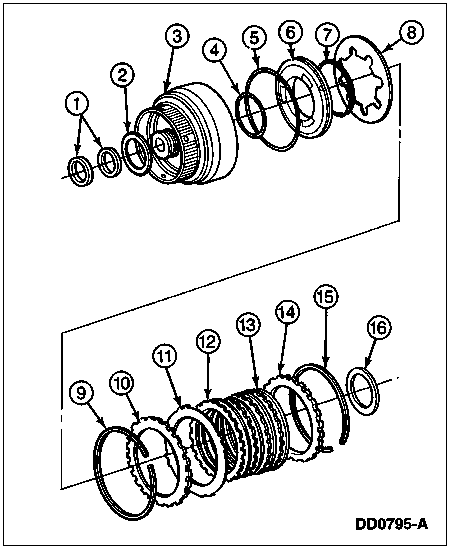
| Item | Part Number | Description |
|---|
| 1 | 7D019 | Forward Clutch Cylinder Seals |
| 2 | 7F374 | Forward Clutch Needle Thrust Bearing Assy (No. 8B) |
| 3 | 7A360 | Forward Clutch Cylinder |
| 4 | 7A548 | Forward Clutch Piston, Inner Seal |
| 5 | 7A548 | Forward Clutch Piston, Outer Seal |
| 6 | 7A262 | Forward Clutch Piston |
| 7 | 7D256 | Forward Clutch Piston Apply Ring |
| 8 | 7B070 | Forward Clutch Piston Return Spring |
| 9 | 377127-S | Forward Clutch Piston Return Spring Retaining Ring |
| 10 | 7B066 | Forward Clutch Pressure Plate — Bottom |
| 11 | 7E085 | Forward Clutch Pressure Spring |
| 12 | 7B442 | Forward Clutch External Spline, Plate — Steel |
| 13 | 7B164 | Forward Clutch Internal Spline Plates — Friction |
| 14 | 7B066 | Forward Clutch Pressure Plate — Top |
| 15 | 377127-S | Forward Clutch Pressure Plate Retaining Ring (Selective Fit) |
| 16 | 7D234 | Forward Clutch Thrust Bearing (No. 9A) |
Disassembly
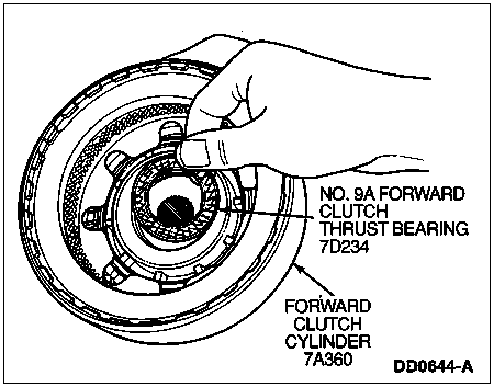
Remove the No. 9A forward clutch thrust bearing from the inner face of the forward clutch cylinder.
Remove No. 8B forward clutch needle bearing assembly.
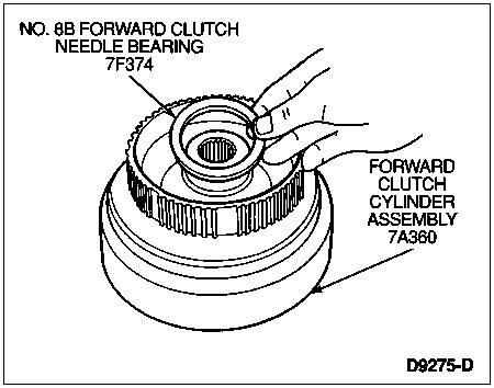
Remove two interlocking forward clutch cylinder seals from grooves.
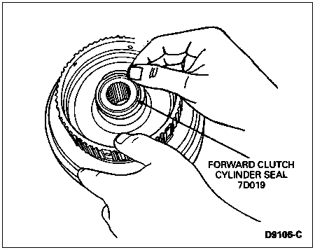
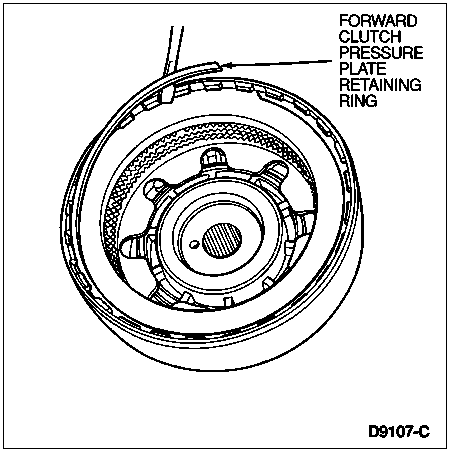
Remove forward clutch pressure plate retaining ring.
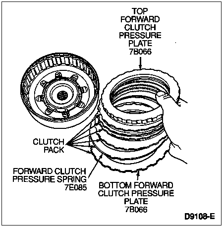
Remove top forward clutch pressure plate, three or four plate clutch pack, (depending on vehicle application), forward clutch pressure spring and plate. Tag for reassembly.
Remove forward clutch piston return spring retaining ring.
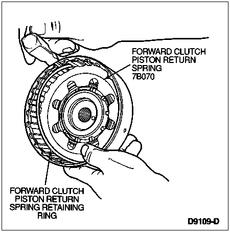
Remove forward clutch piston return spring.
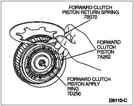
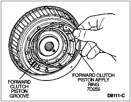
Remove forward clutch piston apply ring from forward clutch piston groove.
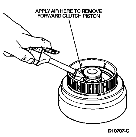
Remove forward clutch piston from cylinder using compressed air.
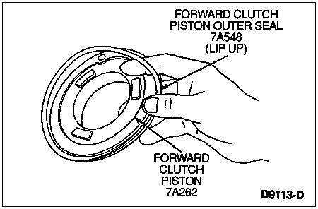
Remove outer forward clutch piston seal from forward clutch piston.
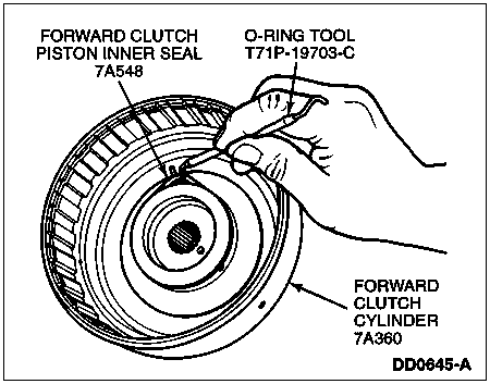
Remove forward clutch piston inner seal from the forward clutch cylinder using O-Ring Tool T71P-19703-C.
Assembly
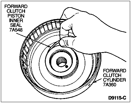
Install forward clutch piston inner seal onto front clutch cylinder.
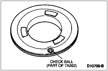
Inspect forward clutch piston check ball for freedom of movement and proper seating. Replace forward clutch piston assembly if necessary. Clean with a suitable solvent if necessary.
Install forward clutch piston outer seal on forward clutch piston with lip facing upward as shown.

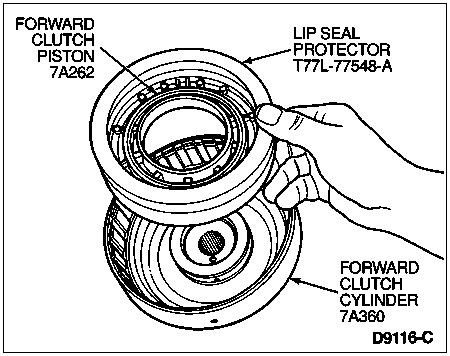
Install forward clutch piston into forward clutch cylinder using Lip Seal Protector T77L-77548-A.
Install steel forward clutch piston apply ring into forward clutch piston groove.

 CAUTION: To ensure durability, the notch between the piston return spring fingers must be positioned so that both ends of the forward clutch piston apply ring are visible.
Install forward clutch piston return spring with the spring fingers against the forward clutch piston apply ring.

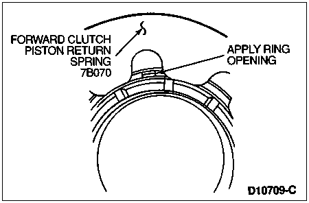
Install forward clutch piston return spring retaining ring. Verify proper seating in groove.

Install bottom forward clutch pressure plate (beveled face downward).
Install forward clutch pressure spring.
NOTE: Soak the clutch plates with clean Motorcraft MERCON® Multi-Purpose Automatic Transmission Fluid XT-2-QDX or MERCON® equivalent.
Install clutch pack (the number of plates are model dependent).
Install top forward clutch pressure plate.

Install forward clutch pressure plate retaining ring.
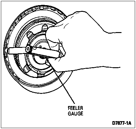
Using feeler gauge, check stack-up clearance in three positions 120 degrees apart. If clearance is not 1.40-0.76 mm (0.055-0.030 inch), install correct retaining ring and recheck clearance. Refer to the Specifications portion of this section for selective snap ring thicknesses and part numbers.
NOTE: Lightly lubricate the needle bearing with petroleum jelly to hold it in place during assembly.
Install No. 8B forward clutch needle bearing assembly with large I.D. radius facing inward.

NOTE: Stagger the interlocking opening on the seals 180 degrees apart when installed.
Install two new cast iron forward clutch cylinder seals in grooves.

NOTE: Lightly lubricate thrust bearing with petroleum jelly to hold it in place during assembly.
Install No. 9A forward clutch thrust bearing on inner face of forward clutch cylinder, with black side facing up.

Output Shaft
Disassembly and Assembly
NOTE: The anti-seepage seal on the original equipment output shaft (7060) is intended for shipping purposes only. It is not necessary to remove and reuse this seal when replacing the output shaft.
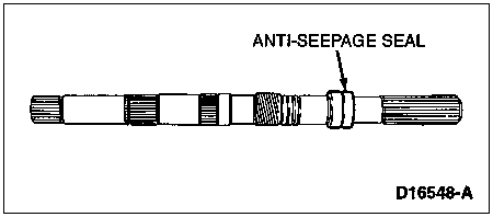
The output shaft cannot be disassembled. The output shaft must be replaced, if damaged.
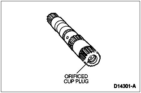
Inspect the output shaft for wear. Make sure the cup plug orifice is clean and free of debris. Service as required.
Forward Planet Assembly
Disassembly
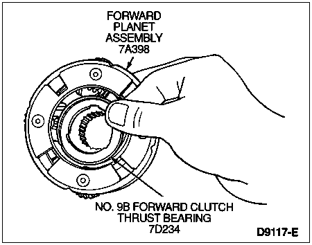
Remove No. 9B forward clutch thrust bearing from forward planet assembly.
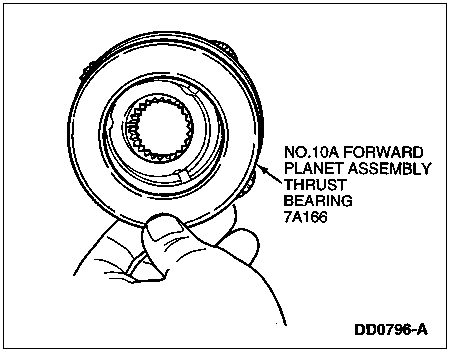
Remove No. 10A forward planet assembly thrust bearing from front side of forward planet assembly.
Assembly
NOTE: Lightly lubricate thrust bearing with petroleum jelly to hold it in place during assembly.
Place No. 10A forward planet assembly thrust bearing on front side of forward planet assembly.

NOTE: Install notched inner race facing outward and large O.D. radius facing inward.
Install No. 9B forward clutch thrust bearing on inner face of forward planet assembly.

Input Shell
Disassembly
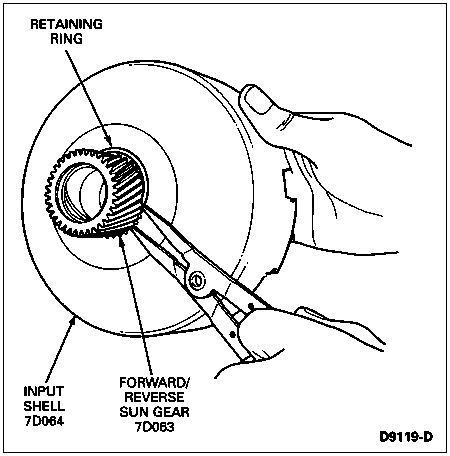
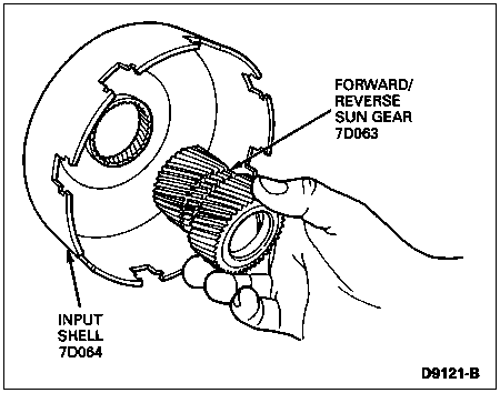
If so equipped, remove and discard retaining ring from forward/reverse sun gear using retaining ring pliers.
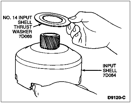
Remove No. 14 input shell thrust washer (7D066) from input shell.
Remove forward/reverse sun gear from input shell.
Assembly
Install forward/reverse sun gear, so that lube hole in gear is between stand-off pads on input shell.

NOTE: If forward/reverse sun gear has no retaining ring, lightly lubricate thrust washer with petroleum jelly to hold it in place during assembly.
Install No. 14 input shell thrust washer onto forward/reverse sun gear.

 CAUTION: Use care not to overextend retaining ring.
If so equipped, Install new retaining ring onto forward/reverse sun gear using retaining ring pliers.

Reverse Planet Assembly
Disassembly
Remove No. 11 rear reverse planet thrust washer.
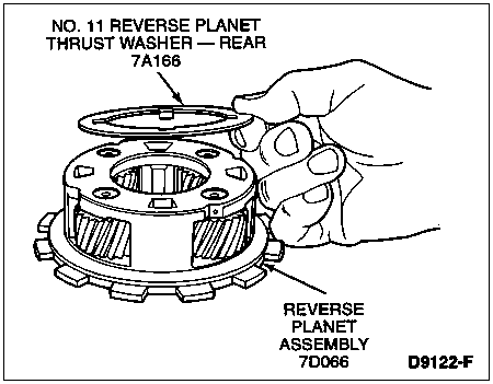
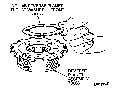
Remove No. 10B front reverse planet thrust washer.
Assembly
NOTE: Lightly lubricate thrust washer with petroleum jelly to hold it in place during assembly.
Install No. 10B front reverse planet thrust washer with tabs positioned in slots on reverse planet (7D006) assembly.
NOTE: Lightly lubricate thrust washer with petroleum jelly to hold it in place during assembly.
Install No. 11 rear reverse planet thrust washer with tabs positioned into slots on reverse planet assembly.

Reverse Clutch
Disassembly and Assembly
The reverse clutch is removed and installed during disassembly and assembly of the transmission (7003). Refer to Transmission in the Disassembly and Assembly portion of this section.
Extension Housing
Disassembly and Assembly
The extension housing (7A039) is disassembled and assembled during the disassembly and assembly of the transmission. Refer to Transmission in the Disassembly and Assembly portions of this section.
Low One-Way Clutch Assembly
Refer to the following disassembled view of the low/reverse one-way clutch assembly and piston for component location and orientation.
Low/Reverse One-Way Clutch Assembly and Piston, Disassembled View
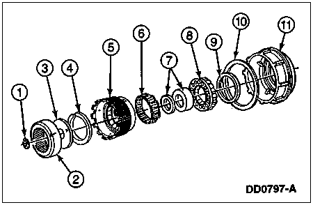
| Item | Part Number | Description |
|---|
| 1 | 387031-S | Output Shaft Retaining Ring |
| 2 | 7A153 | Output Shaft Ring Gear |
| 3 | 7D164 | Output Shaft Hub |
| 4 | 377132-S | Retaining Ring |
| 5 | 7B067 | Reverse Clutch Hub |
| 6 | 7A089 | Low One-Way Clutch Assy |
| 7 | 7G178 | Low/Reverse One-Way Clutch Inner Race and Thrust Bearing Assy (No. 12) |
| 8 | 7D406 | Reverse Clutch Return Spring Assy |
| 9 | 7D404 | Reverse Clutch Piston Inner Lip Seal |
| 10 | 7D403 | Reverse Clutch Piston Outer Lip Seal |
| 11 | 7D402 | Reverse Clutch Piston |
Disassembly
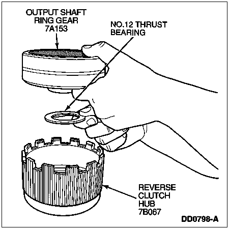
Remove output shaft ring gear (7A153) and No. 12 thrust bearing from reverse clutch hub.
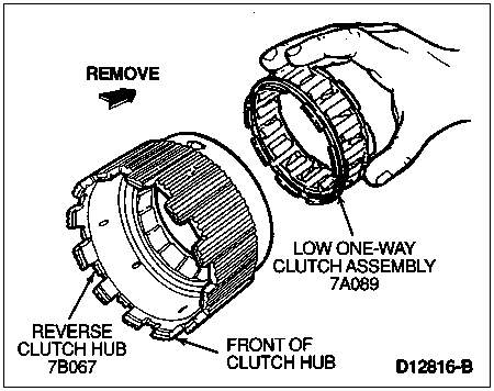
If necessary, remove low one-way clutch assembly from reverse clutch hub.
Rotate low one-way clutch assembly counterclockwise and remove from the rear of the reverse clutch hub.
Assembly
NOTE: Check reverse clutch hub thrust surfaces for scores and reverse clutch hub splines for wear. Replace all worn parts.
NOTE: Inspect outer and inner low/reverse one-way clutch race for scores or damaged surface areas where rollers contact races. Inspect rollers and springs for excessive wear or damage. Inspect spring and cage.
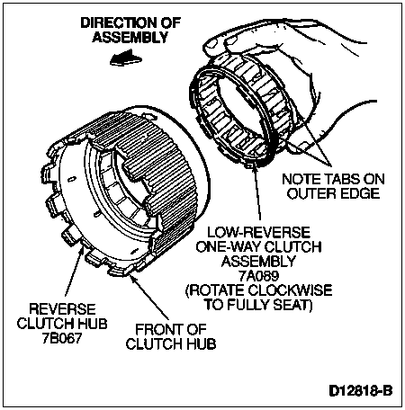
Install the low one-way clutch assembly through the rear of the reverse clutch hub, refer to the illustration for component orientation and direction of assembly. Seat low one-way clutch assembly carefully into reverse clutch hub, and rotate clockwise to seat bearings properly and lock tabs in place against the hub.
Reverse Clutch Piston
Disassembly
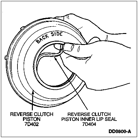
Remove reverse clutch piston outer lip seal.
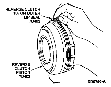
Remove reverse clutch piston inner lip seal.
Assembly
NOTE: Make sure lip on seal faces back side of piston.
Install reverse clutch piston inner lip seal and reverse clutch piston outer lip seal.
Torque Converter Checks
Torque Converter Leakage Check
If welds on the torque converter (7902) indicate leakage, remove the torque converter and make the following check.
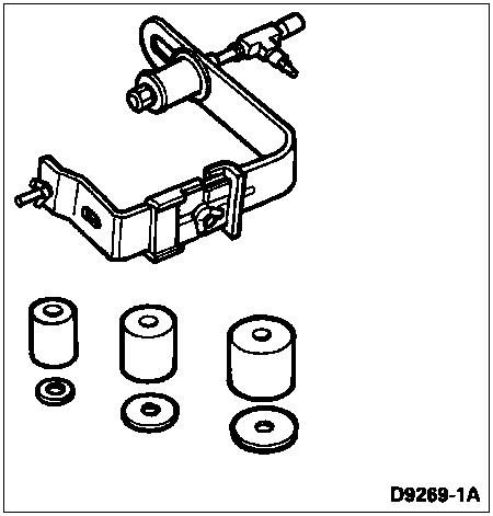
Assemble Rotunda Leak Test Kit 014-R1067 or equivalent to the torque converter. Test the torque converter for leaks, following the directions supplied with the kit.
Rotunda Leak Test Kit 014-R1067
One-Way Clutch Check
SPECIAL SERVICE TOOL(S) REQUIRED| Description | Tool Number |
|---|
| Converter Clutch Holding Tool | T77L-7902-R |
| Converter Clutch Torquing Tool | T76L-7902-C |
Insert the Converter Clutch Holding Tool T77L-7902-R in one of the grooves in the stator thrust washer.
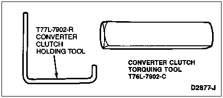
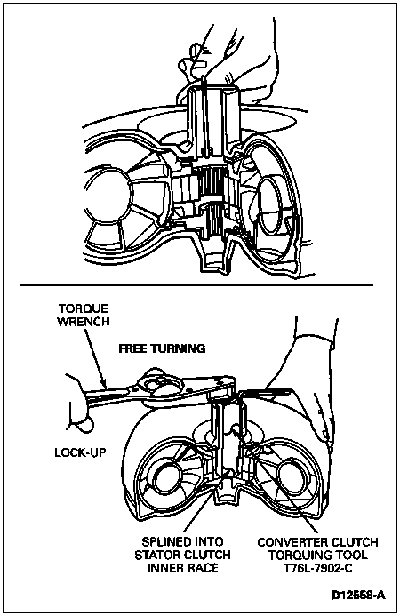
Insert Converter Clutch Torquing Tool T76L-7902-C in converter pump drive hub to engage one-way clutch inner race.
Attach a toque wrench to the converter clutch torquing tool. With the converter clutch holding tool held stationary, turn the torque wrench counterclockwise. The converter one-way clutch should lock up and hold a 13 Nm (10 lb-ft) force. The converter one-way clutch should rotate freely in a clockwise direction until torquing tool contacts the holding tool. Try the clutch for lock up and hold in at least five different locations around the converter.
If the clutch fails to lock up and hold a 13 Nm (10 lb-ft) torque, replace the torque converter unit.
End Play Check
SPECIAL SERVICE TOOL(S) REQUIRED| Description | Tool Number |
|---|
| End Play Checking Tool | T80L-7902-A |
Insert End Play Checking Tool T80L-7902-A into the converter pump drive hub until it bottoms.
Expand the sleeve in the turbine spline by tightening the threaded inner post until the tool is securely locked into the spline.

NOTE: Dial Indicator must be between ridges in next step.
Attach Dial Indicator with Bracketry TOOL-4201-C or equivalent to the tool. Position the indicator button on the torque converter housing as shown in the following illustration and set the dial face at 0 (zero).
Lift the tool upward as far as it will go and note the indicator reading. The indicator reading is the total end play which the turbine and stator share. Replace the converter unit if the total end play exceeds the limits. Refer to end play specifications listed below.
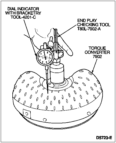
Loosen the threaded inner post to free the tool, and then remove the tool from the converter.
TORQUE CONVERTER END PLAY (E4OD)| Engine | New or Rebuilt Torque Converter | Used Torque Converter |
|---|
| mm | Inch | mm | Inch |
|---|
| Gas | 0.35-0.96 | 0.014-0.038 | 1.8 Max. | 0.071 Max. |
| 7.3L DI Diesel | 0.60-1.21 | 0.024-0.048 | 2.0 Max. | 0.079 Max. |
Note: If the torque converter is replaced, be aware that the torque converter is model dependent.
Stator to Impeller Interference Check (Gasoline Engine Applications Only)
NOTE: Stator support can remain in pump assembly during this test.
Position the stator support on a bench with the spline end of the shaft pointing up.
NOTE: Torque converter must be positioned on top of stator as shown in the following illustration to properly perform this check.
Mount a converter on the stator support with the splines on the one-way clutch inner race engaging the mating splines of the stator support.
Hold the stator support stationary and try to rotate the torque converter counterclockwise. The torque converter should rotate freely without any signs of interference or scraping within the torque converter.
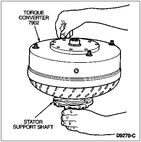
If there is an indication of scraping, the trailing edges of the stator blades might be interfering with the leading edges of the impeller blades. In such cases, replace the torque converter.
Stator to Turbine Interference Check (Gasoline Engine Applications Only)
NOTE: Stator support can remain in pump assembly during this test.
Position the torque converter on the bench stud side down.
Install a stator support to engage the mating splines of the stator support shaft.
Install the input shaft, engaging the splines with the turbine hub.
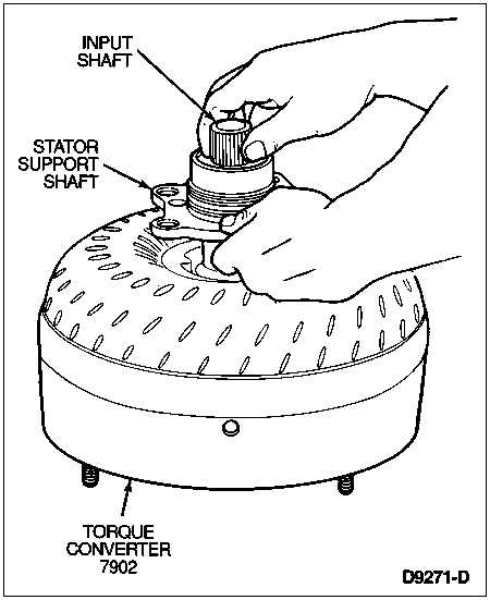
Hold the stator shaft stationary and attempt to rotate the turbine with the input shaft. The turbine and lock-up clutch assemblies should rotate in both directions, not exceeding maximum torque of 9.5 Nm (7 lb-ft), without any signs of metallic interference or scraping noise.
If interference exists, the stator front thrust washer may be worn, allowing the stator to hit the turbine. In such cases, the torque converter must be replaced.
Check the converter crankshaft pilot for nicks or damaged surfaces that can cause interference when installing the transmission to the engine. Check the converter impeller hub for nicks or sharp edges that can damage the pump seal.
![]() CAUTION: Be careful not to damage the case bore while removing the bushing.
CAUTION: Be careful not to damage the case bore while removing the bushing.


