Drain the cooling system. Refer to Section 03-03.
Section 03-01C: Engine, 7.3L Diesel | 1997 F-250 Heavy Duty, F-350 and F-Super Duty Workshop Manual |
Removal
Disconnect the battery ground cable. On vehicles equipped with dual batteries, refer to Section 14-01.
Drain the water fuel separator.
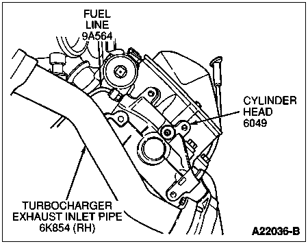
Disconnect the fuel supply lines from the rear of cylinder head (6049).
Drain the cooling system. Refer to Section 03-03.
Remove one generator bolt and position the heater hose aside.
Remove the drive belt (8620). Refer to Section 03-05.
Disconnect the generator electrical connectors.
Remove the generator bracket retaining bolts.
Remove the generator bracket (10A313) (with generator (GEN) (10300) attached).
Remove the oil level indicator bracket bolts, bracket and oil level dipstick (6750).
Remove the oil level indicator tube.
Remove the manifold absolute pressure sensor (MAP sensor) (9F479) and screws. Position aside.
Disconnect the two engine harness electrical connectors from the valve cover gasket (6584).
Remove the valve cover bolts and valve cover (6582).
Disconnect the electrical connectors from the fuel injector nozzle tip (9E527) and glow plugs.
Remove the valve cover gasket.
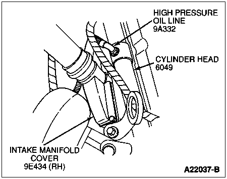
Remove the high pressure oil line to the right cylinder head.
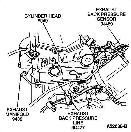
Remove the exhaust back pressure line.
Remove the three glow plug relay bracket nuts and the ground wire.
Disconnect the heater hose from the right cylinder head.
Remove the heater plenum screws, nuts, and clip. Remove the outer half of heater plenum. Refer to Section 12-02 in the Body, Chassis Manual.

 CAUTION: Make sure to retrieve the fuel injector copper washer, located at the tip of the fuel injector, during removal.
NOTE: When removing the fuel injectors it is important that all three injector O-rings and the injector tip copper washer are retrieved from the injector bore.
NOTE: If injector is to be replaced, refer to Section 03-04C for proper injector identification.
Remove the fuel injectors. Refer to Section 03-04C.
Remove the rocker arms (6564) and push rods (6565).
Raise vehicle.
Remove exhaust manifold. Refer to Exhaust Manifold in the Removal and Installation portion of this section.
Lower vehicle.
Remove the ground strap bolt at the rear of the cylinder head.
Disconnect the fuel return line at the front of the cylinder head.
Remove the four inboard fuel injector shoulder bolts.
Remove the cylinder head bolts.
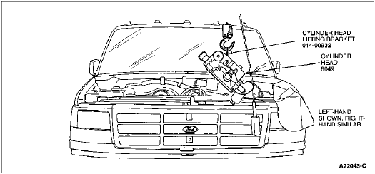
Install the Rotunda Cylinder Head Lifting Bracket 014-00932 or equivalent.
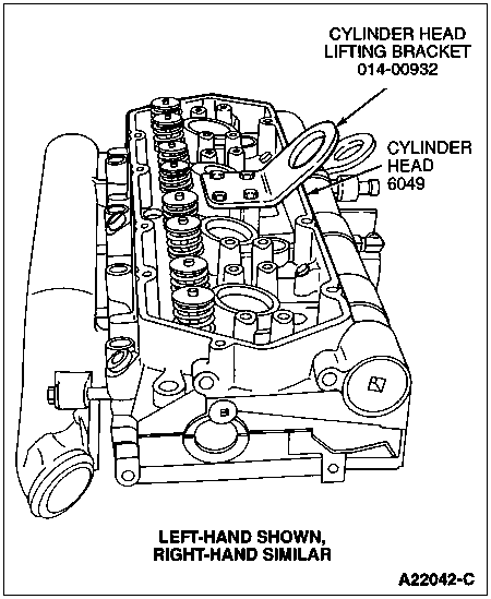
Remove the cylinder head and head gasket (6051).
Cylinder Head Removal
Clean the cylinder block mating surface.
Clean the cylinder head mating surface.
Inspect the cylinder head and cylinder block deck. Refer to Cylinder Heads, Inspection and Cylinder Head Flatness in the Cleaning and Inspection portion of this section.
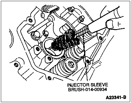
To make sure the fuel injector O-rings seat properly, clean fuel injector bore using Rotunda Injector Sleeve Brush 014-00934 or equivalent. Clean any debris from fuel injector bore.
Installation
Install head gasket over dowel sleeves and onto the cylinder head surface.
Install the cylinder head. Do not damage the gasket.
Remove the Rotunda Cylinder Head Lifting Bracket 014-00932 or equivalent.
CAUTION: Do not use too much engine oil on the threads or damage to the threads and poor sealing may result. Do not use anti-seize compound, grease or any other lubricants except engine oil on the cylinder head bolt threads because they will affect the true torque value reading of the bolts.
Lightly lubricate the cylinder head retaining bolt threads and flanges with clean engine oil.
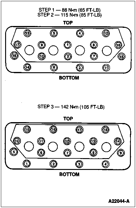
Install the cylinder head retaining bolts in sequence to the specified torque. Refer to the following illustration.
Install the four inboard fuel injector shoulder bolts. Tighten shoulder bolts to 12 Nm (9 lb-ft).
Connect the fuel return line at the front of the cylinder head.
Install the ground strap bolt at the rear of the cylinder head.
Install the exhaust manifold. Refer to Exhaust Manifold in the Removal and Installation portion of this section.
Install the fuel injectors. Refer to Section 03-04C.
CAUTION: Failure to follow the next step of this procedure could result in bent valves, causing severe engine damage.
Rotate engine until the mark on the crankshaft vibration damper (6316) is at 11 o'clock to prevent valve damage when installing rocker arms.
Install the push rods (copper end up), rocker arms and rocker arm bolts (6A527). Tighten the rocker arm bolts to 27 Nm (20 lb-ft).
Install the oil rail drain plugs. Tighten oil rail drain plug to 6 Nm (53 lb-in).
Install the heater plenum, screws, nuts, and clip.
Install the heater hose at the right cylinder head.
Install the glow plug relay bracket, three nuts and ground wire.
Install the exhaust back pressure line.
Install the high-pressure oil supply line to the right cylinder head. Tighten oil supply fitting to 26 Nm (19 lb-ft).
Install the oil level indicator tube.
Install the oil level indicator tube bracket, bolts and oil level dipstick.
Install MAP sensor and screws.
Install the valve cover gasket.
Connect electrical connectors to the fuel injectors (9F593) and glow plugs.
Install the valve cover and bolts. Tighten bolts to 11 Nm (8 lb-ft).
Connect the two electrical connectors to the valve cover gasket.
Install the generator bracket (with generator attached) and retaining bolts. Tighten the generator bracket bolts to 40-55 Nm (30-40 lb-ft).
Connect the generator electrical connectors.
Install the heater hose clip at the generator and install the generator retaining bolt. Tighten the bolt to 40-55 Nm (30-40 lb-ft).
Install the drive belt. Refer to Section 03-05.
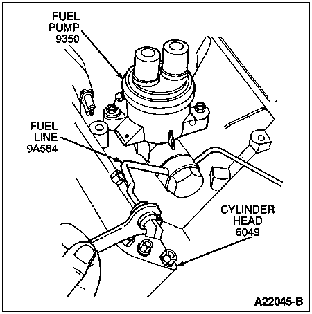
Install the fuel supply line to the rear of cylinder head.
Tighten the fuel supply line to the rear of cylinder head. Tighten the fittings to standard torque specification listed at the end of this section.
Refill the cooling system. Refer to Section 03-03.
NOTE: When the battery (10655) has been disconnected and reconnected, some abnormal drive symptoms may occur while the powertrain control module (PCM) (12A650) relearns its adaptive strategy. The vehicle may need to be driven 16 km (10 miles) or more to relearn the strategy.
Reconnect the battery ground cable. On vehicles equipped with dual batteries, refer to Section 14-01.