Section 06-06: Brake System, Hydraulic | 1996 F-150, F-250, F-350, Bronco and F-Super Duty Workshop Manual |
ADJUSTMENTS
Brake Load Sensor Proportioning Valve
Inspect the vehicle to determine if the rear suspension has been modified. Refer to Section 04-02. If the rear suspension has been modified, the ride height and spring rate have been altered and the brake load sensor proportioning valve cannot work properly.
Unmodified Suspension
If there is a customer concern regarding premature front disc brake pad wear that cannot be attributed to other causes, replace the brake load sensor proportioning valve (2B547) and linkage. Refer to the procedure in this section.
Modified Suspension
If a brake load sensor proportioning valve is present and there is a customer concern regarding premature front disc brake pad wear that cannot be attributed to other causes, perform the following procedure:
Raise and support the vehicle.
Remove the brake load sensor proportioning valve shaft nut and disconnect the linkage from the shaft.
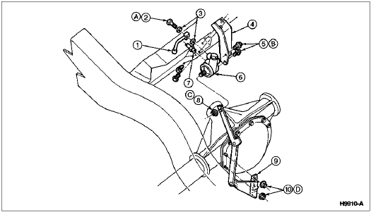
Brake Load Sensor Proportioning Valve and Linkage

| Item | Part Number | Description |
| 1 | 2282 | Rear Brake Hose |
| 2 | 385116-S2 | Flow Bolt |
| 3 | 388949-S | Copper Washers |
| 4 | 2B526 | Brake Load Sensor Proportioning Valve Bracket |
| 5 | 56522-S100 | Brake Load Sensor Proportioning Valve Bolts |
| 6 | 2B547 | Brake Load Sensor Proportioning Valve |
| 7 | 2265 | Brake Line (from Master Cylinder) |
| 8 | 379930-S2 | Brake Load Sensor Proportioning Valve Nut |
| 9 | 2C193 | Valve Linkage |
| 10 | 379930-S2 | Valve Linkage-to-Differential Housing Nuts |
| A | — | Tighten to 23-34 Nm
(17-25 Lb-Ft) |
| B | — | Tighten to 30-41 Nm
(22-30 Lb-Ft) |
| C | — | Tighten to 15-20 Nm
(11-15 Lb-Ft) |
| D | — | Tighten to 34-46 Nm
(25-34 Lb-Ft) |
Remove the two valve linkage-to-differential housing nuts and the valve linkage.
Return the linkage to the customer.
Install the valve linkage-to-differential housing nuts and tighten to 34-46 Nm (25-34 lb-ft).
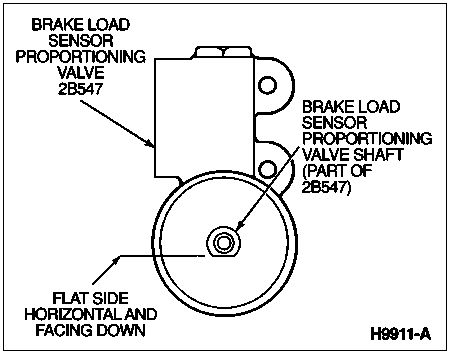
Rotate the brake load sensor proportioning valve shaft one full turn in either direction and position the shaft so that the flat is horizontal and facing down.

Rotate the brake load sensor proportioning valve shaft counterclockwise 90 degrees so that the flat is vertical.

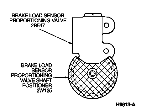
Install the brake load sensor proportioning valve shaft positioner so that the flat on the shaft is still vertical and the positioner is fully seated on the valve body.

Install the brake load sensor proportioning valve shaft nut and tighten to 11-14 Nm (8-10 lb-ft).
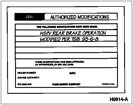
Install an "Authorized Modification" decal on the brake booster listing the modification as follows: HSPV REAR BRAKE OPERATION MODIFIED.
Obtain an Authorized Modifications Decal and list the date, dealer number, and a summary of the alterations performed. Apply the decal near the Vehicle Emission Control Information Decal and cover it with a clear plastic decal shield.


