Section 06-06: Brake System, Hydraulic | 1996 F-150, F-250, F-350, Bronco and F-Super Duty Workshop Manual |
![]() CAUTION: If the linkage is disconnected from the brake load sensor proportioning valve (2B547), the proper indexing will be lost and a new brake load sensor proportioning valve must be installed. The new brake load sensor proportioning valve will have the shaft preset and secured internally. If the valve shaft of the valve turns freely, DO NOT USE. The brake load sensor proportioning valve is not to be repaired or disassembled. It must be replaced as a complete assembly. If the linkage is damaged or broken and requires replacement, a new brake load sensor proportioning valve must also be installed.
CAUTION: If the linkage is disconnected from the brake load sensor proportioning valve (2B547), the proper indexing will be lost and a new brake load sensor proportioning valve must be installed. The new brake load sensor proportioning valve will have the shaft preset and secured internally. If the valve shaft of the valve turns freely, DO NOT USE. The brake load sensor proportioning valve is not to be repaired or disassembled. It must be replaced as a complete assembly. If the linkage is damaged or broken and requires replacement, a new brake load sensor proportioning valve must also be installed.
NOTE: When servicing other rear suspension components, (axle assembly, rear springs (5560), fuel tank (9002), etc.), remove the two nuts attaching the sensing valve linkage to the rear axle cover plate. This will eliminate the need to replace the brake load sensor proportioning valve.
NOTE: Any change to the vehicle rear suspension which alters curb ride height or spring deflection rate (increased capacity rear springs, addition of spacers, etc.) may change the function of the brake load sensor proportioning valve and alter the system braking performance.
Removal
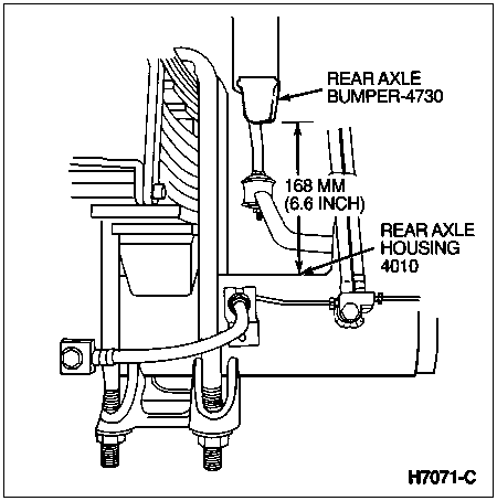
With the rear wheels (1007) on the ground, lift the frame (5005) to obtain a 168mm (6.6-inch) clearance between the bottom edge of the rear axle bumper (4730) and the top of the rear axle housing (4010) (both sides). The suspension is now in the correct position for installing the pre-indexed brake load sensor proportioning valve.

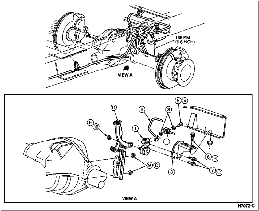
Remove the nut holding the linkage arm to the brake load sensor proportioning valve and disconnect the linkage arm.
Remove the flow bolt holding the rear brake hose (2282) to the brake load sensor proportioning valve.
Disconnect the brake tube from the brake load sensor proportioning valve.
Remove the two bolts securing the brake load sensor proportioning valve to mounting bracket, remove the brake load sensor proportioning valve.
Installation
Place the brake load sensor proportioning valve on its mounting bracket. Install the two mounting bolts and tighten to 30-40 Nm (22-30 lb-ft).
Install the rear brake hose using new copper washers. Tighten the flow bolt to 23-34 Nm (17-25 lb-ft).
Install the brake tube to the lower port on the brake load sensor proportioning valve and tighten securely.
Position the linkage arm on the brake load sensor proportioning valve and tighten the retaining nut to 15-20 Nm (11-15 lb-ft).
Bleed the brakes. Refer to Service Procedures in this section. Check for proper brake operation.

| Item | Part Number | Description |
|---|---|---|
| 1 | 2B547 | Brake Load Sensor Proportioning Valve |
| 2 | 2265 | Brake Tube |
| 3 | 388949-S | Copper Washer |
| 4 | 385116-S2 | Bolt |
| 5 | 2282 | Rear Brake Hose |
| 6 | N605789 | Bolt |
| 7 | 56522 | Bolt |
| 8 | 2B256 | Bracket |
| 9 | 379930 | Nut |
| 10 | 379930 | Nut |
| 11 | 2C193 | Linkage |
| A | — | Tighten to 23-34 Nm (17-25 Lb-Ft) |
| B | — | Tighten to 26-40 Nm (19-30 Lb-Ft) |
| C | — | Tighten to 30-40 Nm (22-30 Lb-Ft) |
| D | — | Tighten to 34-46 Nm (25-34 Lb-Ft) |
| E | — | Tighten to 15-20 Nm (11-15 Lb-Ft) |