Section 04-00: Suspension, Service | 1996 F-150, F-250, F-350, F-Super Duty and Bronco Workshop Manual |
Refer to Front Wheel Alignment Specifications in the Specifications portion of this section.
![]() CAUTION: Do not bend axles or radius arms to change alignment.
CAUTION: Do not bend axles or radius arms to change alignment.
After front wheel alignment has been checked, make the necessary adjustments as described below.
Caster and Camber, F-150, F-250, F-350 4x2 Ball Joint System
| Description | Tool Number |
|---|---|
| Pitman Arm Puller | T64P-3590-F |
Measure vehicle caster and camber.
If adjustment is necessary, determine the amount of caster/camber in the adjuster installed in the vehicle.
NOTE: The assembly plant sometimes builds vehicles with adjusters that are not zero-degree type to control alignment. The following chart shows the alignment changes that will occur if the vehicle was originally built with zero-degree adjusters. Always check to see which adjuster has been installed (and its orientation) before making changes.
Refer to the chart.

| Service Adjuster Type (Degrees) | Position Slot in Axle (Degrees) | LH Axle | RH Axle | ||
|---|---|---|---|---|---|
| Camber Change (Degrees) | Caster Change (Degrees) | Camber Change (Degrees) | Caster Change (Degrees) | ||
| 1/2 | 0 | -0.5 | 0 | +0.5 | 0 |
| 1 | 0 | -1.0 | 0 | +1.0 | 0 |
| 1-1/2 | 0 | -1.5 | 0 | +1.5 | 0 |
| 1/2 | 45 | -0.25 | +0.25 | +0.25 | +0.25 |
| 1 | 45 | -0.75 | +0.75 | +0.75 | +0.75 |
| 1-1/2 | 45 | -1.00 | +1.00 | +1.00 | +1.00 |
| 1/2 | 90 | 0 | +0.5 | 0 | +0.5 |
| 1 | 90 | 0 | +1.0 | 0 | +1.0 |
| 1-1/2 | 90 | 0 | +1.5 | 0 | +1.5 |
| 1/2 | 135 | +0.25 | +0.25 | -0.25 | +0.25 |
| 1 | 135 | +0.75 | +0.75 | -0.75 | +0.75 |
| 1-1/2 | 135 | +1.00 | +1.00 | -1.00 | +1.00 |
| 1/2 | 180 | +0.5 | 0 | -0.5 | 0 |
| 1 | 180 | +1.0 | 0 | -1.0 | 0 |
| 1-1/2 | 180 | +1.5 | 0 | -1.5 | 0 |
| 1/2 | 225 | +0.25 | -0.25 | -0.25 | -0.25 |
| 1 | 225 | +0.75 | -0.75 | -0.75 | -0.75 |
| 1-1/2 | 225 | +1.00 | -1.00 | -1.00 | -1.00 |
| 1/2 | 270 | 0 | -0.5 | 0 | -0.5 |
| 1 | 270 | 0 | -1.0 | 0 | -1.0 |
| 1-1/2 | 270 | 0 | -1.5 | 0 | -1.5 |
| 1/2 | 315 | -0.25 | -0.25 | +0.25 | -0.25 |
| 1 | 315 | -0.75 | -0.75 | +0.75 | -0.75 |
| 1-1/2 | 315 | -1.00 | -1.00 | +1.00 | -1.00 |
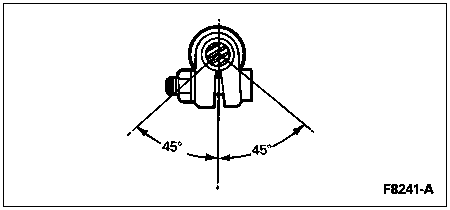
Select a new service adjuster and its orientation in the axle to obtain the optimum caster/camber. Note that the caster change or camber change required to obtain the optimum settings must be added to amounts of caster/camber in the old or production adjuster.
Use this example as a guide. If caster must be reduced 1.0 degree and camber increased +0.75 degree at the LH wheel and the existing adjuster has +0.25 degree caster as installed, select the 1 degree service adjuster and orient the slot 225 degrees from the straight-ahead position. In all cases, select the adjuster and orientation that will bring the alignment closest to the optimal settings.
Raise the vehicle and remove the front wheel.
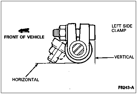
Loosen the pinch bolt at the front suspension upper ball joint and pry the adjuster out of the axle with the blade of a screwdriver. If required, use Pitman Arm Puller T64P-3590-F to remove the adjuster.
Install the new service adjuster. Orient the slot as specified in the chart above.
Tighten the pinch bolt to 67-88 Nm (50-65 lb-ft).
Install front wheel and lower the vehicle.
Check alignment. If not at optimal caster/camber setting, additional adjustment of the rotation of the adjuster may be required to obtain optimal alignment settings.
Once optimal caster/camber has been achieved, reset front toe and clear vision to optimal settings.
Caster and Camber, Bronco and F-150, F-250 4x4 Vehicles
| Description | Tool Number |
|---|---|
| Pitman Arm Puller | T64P-3590-F |
Caster and camber adjustment is provided by means of a series of interchangeable mounting sleeves (camber adjusters) for the upper ball joint stud. There is one adjuster available for caster.
Measure camber with available alignment equipment. If camber is out of specification, proceed to Step 2.
Raise vehicle on hoist and remove the front wheels.
Remove the upper ball joint cotter pin and nut.
Loosen the lower ball joint nut to the end of the stud.
Strike the inside of the spindle near the upper and lower ball joints to break the spindle loose from the ball joint studs.
Remove the camber adjuster sleeve. If required, use Pitman Arm Puller T64P-3590-F to remove the adjuster from the spindle.
Install the replacement service adjuster.
NOTE: Excessive spindle turning efforts, causing poor steering returnability, may result if the fastener tightening sequence described in the following steps is not followed exactly.
Remove the lower ball stud nut and apply Loctite® 242 or equivalent to the lower stud.
Hand-start the lower nut and partially tighten to 54 Nm (40 lb-ft).
Install the new upper nut and tighten to 115-135 Nm (85-100 lb-ft). Advance the nut to the next castellation and install a new cotter pin.
Finish tightening the lower nut to 128-149 Nm (95-110 lb-ft).
Install the wheel and lower the vehicle.
Check camber and set toe according to alignment procedure.
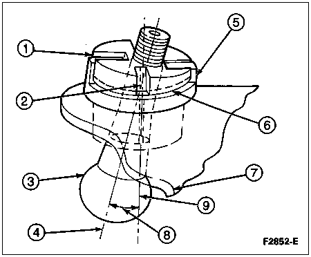
| Item | Part Number | Description |
|---|---|---|
| 1 | � | Slots in Sleeve Engage Lugs to Prevent Rotation of Sleeve Which Would Result in Change of Caster Angle |
| 2 | � | Split in Sleeve Allows Sleeve to Expand When Ball Stud Nut Is Tightened, Locking Sleeve and Ball Stud in Location |
| 3 | � | Ball Stud (Part of 3049) |
| 4 | � | Ball Stud Axis |
| 5 | � | Support Collar with Integral Indexing Lugs Welded to Axle Arm Stamping |
| 6 | � | Step in Sleeve for Engagement of 2-Jaw Puller When Necessary for Removal |
| 7 | � | Axle Stamping (Part of 3002) |
| 8 | � | Angle at Which Sleeve Holds Ball Studs Determines Camber/Caster |
| 9 | � | Sleeve and Support Collar Axis (Also the Ball Stud Axis When 0° Camber Sleeve Is Installed) |
Caster, F-250
The caster angle on F-250 with a leaf spring type suspension can be adjusted by either installing new camber adjusters for the upper ball joint stud or inserting a shim between the spring and axle. Shims are available in zero-degree, one-degree and two-degree increments. The zero-degree shim is used to adjust side-to-side height.
![]() CAUTION: If possible, caster adjustment should always be done on the right front axle to avoid changing front driveshaft alignment.
CAUTION: If possible, caster adjustment should always be done on the right front axle to avoid changing front driveshaft alignment.
To adjust caster, raise the vehicle and support the front axles on safety stands.
Loosen U-bolt nuts and separate spring from axle.
Install caster shims between spring and axle.
Tighten U-bolt nuts until all nuts contact cap. Tighten nuts to 204-282 Nm (150-210 lb-ft).
Caster, F-350 4x4
Caster is adjustable on F-350 4x4. To select the appropriate caster service slug, refer to the following usage chart:
| Caster (Degrees) | Caster Slug Part Number |
|---|---|
| -0.75 | F2TZ-3B440-D |
| -0.5 | F2TZ-3B440-B |
| 0 | F2TZ-3B440-E |
| +0.5 | F2TZ-3B440-A |
| +0.75 | F2TZ-3B440-C |
Camber, F-350 4x4 and F-Super Duty Monobeam Non-Driving Axle
Camber is not adjustable on F-350 4x4 or on the F-Super Duty.
Toe
Refer to Toe Specifications in this section.
The steering linkage has adjustments at the tie rod end (3A131). First, remove the horn pad and make sure the steering wheel is properly installed as described in Section 11-04. With steering wheel locked in place, set toe to correct specification.
Loosen the clamp bolts for the adjusting sleeve.
Rotate the sleeve until the correct toe alignment is obtained.
NOTE: Lubricate clamp fasteners prior to tightening.
With the clamps 4.76mm (3/16 inch) from the end of the sleeve on 4x4 models and centered between the adjusting sleeve lock ring protrusions, position the bolts as described below.

Recheck the toe alignment to make sure no changes occurred as the clamp nuts were tightened.