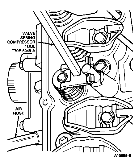
Using Valve Spring Compressor T70P-6049-A, compress the valve spring and remove the valve spring retainer keys, valve spring retainer, and valve spring. Remove and discard the valve stem seal.

Section 03-01C: Engine, 7.5L MFI | 1996 F-250, F-350, F-Super Duty Chassis Cab and Motorhome Workshop Manual |
If the intake valve (6507) or exhaust valve (6505) has not been damaged, the valve spring (6513), valve stem seals (6571), valve spring retainer key (6518) and valve spring retainer (6514) may be replaced by holding the affected intake valve or exhaust valve against its seat using compressed air. Use an appropriate air line tool installed in the spark plug hole. A minimum of 965 kPa (140 psi) line pressure is required.
NOTE: If air pressure does not hold the valve shut, the valve can be damaged and the cylinder head (6049) must be removed and serviced. Refer to Section 03-00.
| Description | Tool Number |
|---|---|
| Valve Spring Compressor | T70P-6049-A |
| Valve Seal Remover | T73P-6571-A |
Removal
Remove the valve cover (6582). Refer to Valve Cover and Gasket in the In-Vehicle Service portion of this section.
Remove the rocker arm (6564) and rocker arm seat (6A528). Refer to Rocker Arm in the In-Vehicle Service portion of this section.
Using Valve Spring Compressor T70P-6049-A, compress the valve spring and remove the valve spring retainer keys, valve spring retainer, and valve spring. Remove and discard the valve stem seal.

If air pressure has forced the piston (6108) to the bottom of the cylinder, any removal of air pressure will allow the intake valve or exhaust valve to fall into the cylinder. A rubber band, tape or string wrapped around the end of adjacent valve stems will prevent this condition and will still allow enough travel to check the intake valve or exhaust valve for binds.
Inspect the valve stem for damage. Rotate the intake valve or exhaust valve and check the stem tip for eccentric movement. Move the intake valve or exhaust valve up and down through normal travel in the valve guide and check the stem for binds. If the intake valve or exhaust valve has been damaged, it will be necessary to remove the cylinder head and service. Refer to Section 03-00 for cylinder head repair procedures.
Installation
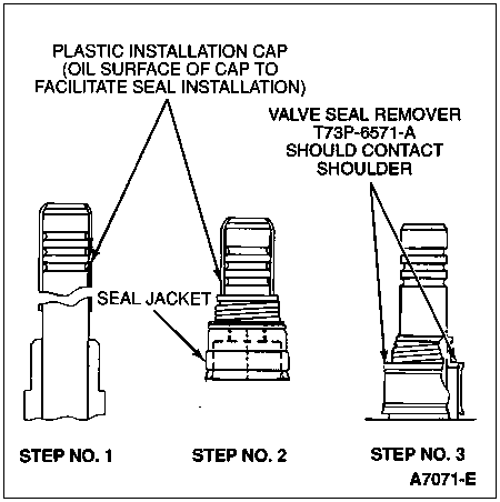
NOTE: Unique exhaust and intake guide-mounted valve stem seals are required and care should be used to install the correct valve stem seal in the appropriate location. The valve stem seals are identified on one end with IN for intake and EX for exhaust.
Install new valve stem seals as follows:
Apply Ford Multi-Purpose Grease D0AZ-19584-AA or equivalent meeting Ford specification ESB-M1C93-B and ESR-M1C159-A to all contact surfaces of the rocker arm. Install push rod (6565). Install rocker arm and rocker arm seat. Refer to Rocker Arm in the In-Vehicle Service portion of this section.
Install the valve cover. Refer to Valve Cover and Gasket in the In-Vehicle Service portion of this section.

Install the spark plug (12405) and tighten to 7-14 Nm (5-10 lb-ft).