Section 01-11: Glass, Frames and Mechanisms | 1996 F-150, F-250, F-350, F-Super Duty and Bronco Workshop Manual |
Switch Tests, Window
Master Window Control Switch
To Test | Connect Self Powered Test Light or Ohmmeter to Terminals | Move Switch to These Positions | A Good Switch Will Indicate |
---|---|---|---|
Power and Ground Checks Before Any Other Tests | 15,400 (LB/BK) and 14, 57 (BK) | All Four Window Switches (All Positions) | Open Circuit |
14, 57 (BK) and 8, 6, 7, 9, 10, 12, 11, 13 | All Four Window Switches (at Rest) | Closed Circuit | |
Left Front Window Circuit | 15,400 (LB/BK) and 8,226 (W/BK) | Up | Closed Circuit |
15,400 (LB/BK) and 6,227 (Y) | Down | Closed Circuit | |
Right Front Window Circuit | 15,400 (LB/BK) and 7,313 (W/Y) | Up | Closed Circuit |
15,400 (LB/BK) and 9,314 (T/LB) | Down | Closed Circuit | |
Left Rear Window Circuit | 15,400 (LB/BK) and 10,317 (GY/O) | Up | Closed Circuit |
15,400 (LB/BK) and 12,316 (Y/LB) | Down | Closed Circuit | |
Right Rear Window Circuit | 15,400 (LB/BK) and 11,320 (R/BK) | Up | Closed Circuit |
15,400 (LB/BK) and 13,319 (Y/BK) | Down | Closed Circuit | |
Window Lock Switch | 15,400 (LB/BK) and 16,170 (R/LB) | Window Lock Switch Towards Door | Open Circuit |
Window Lock Switch Away from Door | Open Circuit |
Pin Number | Circuit | Circuit Function |
---|---|---|
6 | 314 (T/LB) | LF Window Regulator Switch to RF Window Regulator Motor |
7 | 226 (W/BK) | LF Window Regulator Switch to LF Window Regulator Motor |
8 | 313 (W/Y) | LF Window Regulator Switch to RF Window Regulator Motor |
9 | 227 (Y) | LF Window Regulator Switch to LF Window Regulator Motor |
10 | 320 (R/BK) | LF Window Regulator Switch to RR Window Control Switch |
11 | 317 (GY/O) | LF Window Regulator Switch to LR Window Control Switch |
12 | 319 (Y/BK) | LF Window Regulator Switch to RR Window Control Switch |
13 | 316 (Y/LB) | LF Window Regulator Switch to LR Window Control Switch |
14 | 400 (LB/BK) | Power Window Switch Feed |
15 | 57 (BK) | Ground Circuit |
16 | 170 (R/LB) | Window Regulator Switch Feed |
Single Switch
NOTE: Remove window regulator control switch (14529) from the vehicle as described in Removal and Installation, Window Regulator Control Switch in this section. The raised portion of the switch knob should face right exposing the five terminals.
Use a self-powered test lamp or an ohmmeter to test the power window regulator control switch.
With the window regulator control switch in the neutral position, there should be continuity between terminals 1 and 2, and terminals 3 and 4. Terminal 5 should be disconnected from all other terminals.
When the raised portion of the switch rocker knob is pushed, closing windows, there should be continuity between terminals 1 and 5, and terminals 3 and 4. Terminal 2 should be disconnected from all other terminals.
When the depressed portion of the switch rocker knob is pushed, opening the windows, there should be continuity between terminals 1 and 2, and terminals 4 and 5. Terminal 3 should be disconnected from all other terminals.
If the window regulator control switch does not test as stated, replace window regulator control switch.
Pin Number | Circuit | Circuit Function |
---|---|---|
1 | 314 (T/LB) | Left Front Window Regulator Switch to Right Front Window Regulator Switch |
2 | 334 (R/Y) | Window Regulator Switch to Window Regulator Motor |
3 | 170 (R/LB) | Window Regulator Switch Feed |
4 | 333 (Y/R) | Window Regulator Switch to Window Regulator Motor |
5 | 313 (W/Y) | Left Front Window Regulator Switch to Right Front Window Regulator Motor Switch |
Heated Back Window Switch and Light, Control Assembly Test
Ground Pin 4 and connect a jumper wire between Pins 3 and 2.
Apply power to Pin 2. The indicator should not light.
Momentarily actuate control to the ON position. The indicator should come on and stay on after the control returns to the normal position.
The indicator should go off under the following conditions:
Apply 12 volts power to Pin 5. The ISO bulb should light.
Pin Number | Circuit | Circuit Function |
---|---|---|
1 | 186 (BR/LB) | Heated Back Window Switch to Heated Back Window Grid |
2 | 185 (BK) | Battery Feed to Heated Back Window Switch and Grid |
3 | 8 (O/Y) | Heated Back Window Timing Circuit Feed |
4 | 57 (BK) | Ground Circuit |
5 | 19 (LB/R) | Instrument Panel Lamps Feed |
Tailgate Switch, Instrument Panel-Mounted Bronco Only
NOTE: Remove window regulator control switch from the vehicle, as described in Removal and Installation, Window Regulator Control Switch in this section.
Use a self-powered test lamp, or an ohmmeter to test the window regulator control switch.
With the window regulator control switch in the neutral position, there should be continuity between terminals 1 and 2, and terminals 3 and 4. Terminal 5 should be disconnected from all other terminals.
When the switch rocker knob is pushed up to close the tailgate window, there should be continuity between terminals 1 and 2, and terminals 4 and 5. Terminal 3 should be disconnected from all other terminals.
When the switch rocker knob is pushed down to open the back window glass (42006), there should be continuity between terminals 2 and 5, and terminals 3 and 4. Terminal 1 should be disconnected from all other terminals.
If the window regulator control switch does not test as stated, replace the switch.
Pin Number | Circuit | Circuit Function |
---|---|---|
1 | 57 (BK) | Ground Circuit |
2 | 405 (P/LB) | Window Regulator Switch to Back Window Switch |
3 | 57 (BK) | Ground Circuit |
4 | 404 (P/LG) | Window Regulator Switch to Back Window Switch |
5 | 400 (LB/BK) | Power Window Switch Feed |
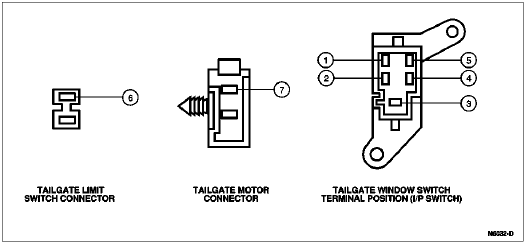
Tailgate Window Regulator Control Switch, Tailgate-Mounted
Testing of the tailgate-mounted window switch can be performed with the switch installed in the vehicle. Use a self-powered test lamp or an ohmmeter.
With the switch in the neutral position, there should be continuity between terminals 1, 2 and 3.
With the back window glass up, there should be continuity between terminals 1 and 5, and 2 and 4.
With back window glass down, there should be continuity between terminals 2 and 5, and 3 and 4.
If the switch does not test as stated, replace switch.
Pin Number | Circuit | Circuit Function |
---|---|---|
1 | 57 (BK) | Ground Circuit |
2 | 405 (P/LB) | Window Regulator Switch to Back Window Switch |
3 | 57 (BK) | Ground Circuit |
4 | 404 (P/LG) | Window Regulator Switch to Back Window Switch |
5 | 400 (LB/BK) | Power Window Switch Feed |
6 | 407 (T/BK) | Window Regulator Switch Rear to Limit Switch |
7 | 333 (Y/R) | Window Regulator Switch to Window Regulator Motor |
Window Regulator Electric Drive
To test window regulator electric drive current draw, remove the front door trim panel (23942) or tailgate trim panel. Refer to Section 01-05.
Disconnect the window regulator electric drive lead.
Disconnect the window regulator control switch from the window regulator electric drive.
Supply power to window regulator electric drive lead connector with an ammeter in series.
NOTE: The current draw for the no-load test should not exceed four amps and should not fluctuate. Reversal of the window regulator electric drive wire connections will reverse the direction of window regulator electric drive rotation.
Operate the window regulator electric drive and observe the current draw.
Replace the window regulator electric drive if the current draw exceeds four amps.
If the window regulator control switch does not test as stated, replace the switch.
Heated Back Window Grid Wire Test
Using a strong light inside vehicle, visually inspect wire grid from outside. A broken grid wire will appear as a brown spot.
Run engine at idle. Set the heated back window switch and light (18C621) to ON. The indicator lamp should come on.
Working inside vehicle with Rotunda Digital Volt-Ohmmeter 014-00407 or equivalent, contact broad (bus bars) red-brown strips on sides of rear window. The meter should read 10-13 volts. A lower voltage reading indicates a loose ground wire (pigtail) connection at grounded side of glass.
Contact a good ground point with negative lead of meter. The voltage reading should not change.
With negative lead of the meter grounded, touch each grid line of heated back window at its midpoint with positive lead. A reading of approximately 6 volts indicates that the line is good. A reading of zero volts indicates that the line is broken between midpoint and the positive side of the grid line. A reading of 12 volts indicates that the circuit is broken between midpoint of grid line and ground.