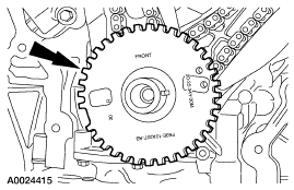
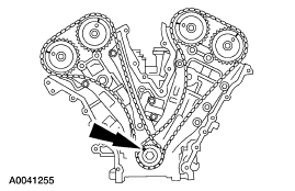
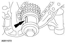
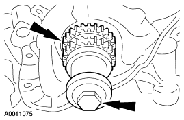
CAUTION: This pulse wheel is used in several different engines. Install the pulse wheel with the keyway in the slot stamped "20-25-34Y-30M" (color blue).
SECTION 303-01B: Engine — 3.0L (4V) | 2002 Escape Workshop Manual |
IN-VEHICLE REPAIR | Procedure revision date: 10/21/2002 |
Removal
CAUTION: This pulse wheel is used in several different engines. Install the pulse wheel with the keyway in the slot stamped "20-25-34Y-30M" (color blue).
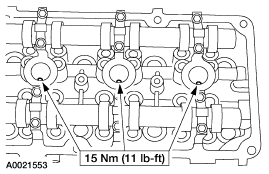
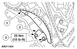
NOTE: RH shown, LH similar.
Remove the LH and the RH spark plugs.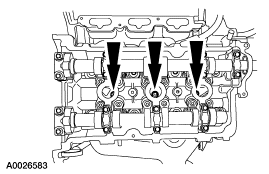
Installation
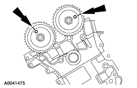
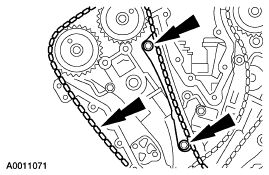
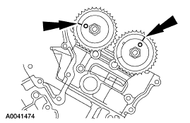
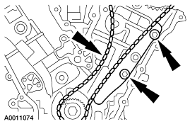
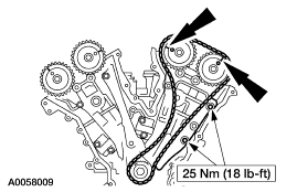
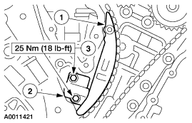
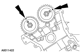
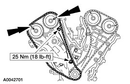
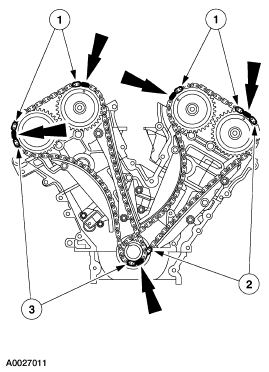
NOTE: Install the sprockets with the timing marks out.
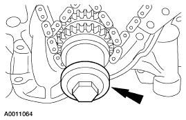
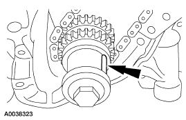
Install the crankshaft sprockets.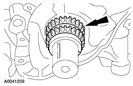
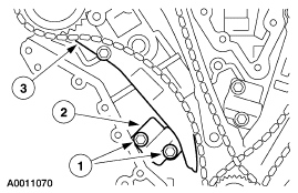
NOTE: LH shown, RH similar.
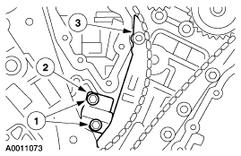
Position the chain tensioner in a soft-jawed vise.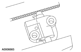
NOTE: LH shown, RH similar.
Hold the chain tensioner ratchet lock mechanism away from the ratchet stem with a small pick.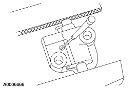
CAUTION: During tensioner compression, do not release the ratchet stem until the tensioner piston is fully bottomed in its bore or damage to the ratchet stem will result.
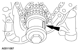
CAUTION: This pulse wheel is used in several different engines. Install the pulse wheel with the keyway in the slot stamped "20-25-34Y-30M" (color blue).
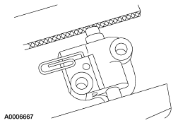
NOTE: RH shown, LH similar.
Install the LH and the RH spark plugs.