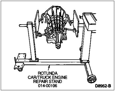
Mount transmission on Rotunda Car/Truck Engine Repair Stand 014-00106 or equivalent with the converter assembly removed.
Section 07-01: Transmission, Automatic, E4OD | 1997 F-250 Heavy Duty, F-350 and F-Super Duty Workshop Manual |
Refer to the Transmission Disassembled view in the Description and Operation portion of this section.
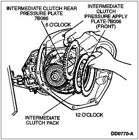
NOTE: During disassembly and assembly of the transmission (7003), the "clock" numbers shown in the following illustrations will be referred to in order to reference the position in the transmission.
| Description | Tool Number |
|---|---|
| Pump Puller Adapter | T89T-70010-A |
| Impact Slide Hammer | T50T-100-A |
| Impact Slide Hammer | T59L-100-B |
| Clutch Spring Fixture | T89T-70010-C |
| Remover/Installer, Clutch Drum | 307-436 |
| Seal Remover | T74P-77248-A |
| Lock Nut Pin Remover | T78P-3504-N |
| Puller | T58L-101-B |
Mount transmission on Rotunda Car/Truck Engine Repair Stand 014-00106 or equivalent with the converter assembly removed.

![]() CAUTION: The input shaft (7017) and overdrive planet assembly are serviced as mating components.
CAUTION: The input shaft (7017) and overdrive planet assembly are serviced as mating components.
Remove input shaft from transmission.

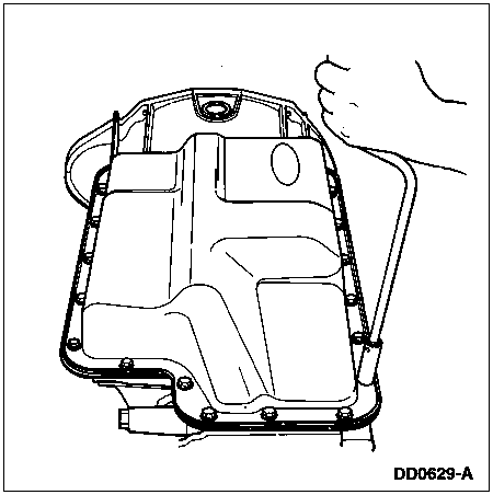
Remove 20 pan retaining bolts using a 10 mm socket. Remove the transmission pan.
![]() CAUTION: Cork gaskets and elastomeric gaskets are not interchangeable. If you remove a cork gasket, replace it with a cork gasket. If you remove an elastomeric gasket, clean, inspect and reuse unless gasket is damaged. Be careful not to cut or bend elastomeric gasket.
CAUTION: Cork gaskets and elastomeric gaskets are not interchangeable. If you remove a cork gasket, replace it with a cork gasket. If you remove an elastomeric gasket, clean, inspect and reuse unless gasket is damaged. Be careful not to cut or bend elastomeric gasket.
Remove, but do not discard, reusable elastomeric transmission pan gasket.

![]() CAUTION: Use care not to scratch or damage aluminum pump bore.
CAUTION: Use care not to scratch or damage aluminum pump bore.
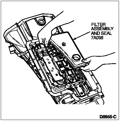
NOTE: After removal, discard filter assembly and seal.
Remove filter assembly and seal by carefully pulling and rotating filter as necessary. If seal remains in bore, carefully remove using a screwdriver.
Remove 11 accumulator body assembly bolts using an 8 mm socket and two nuts using a 10 mm socket. Remove accumulator body assembly.
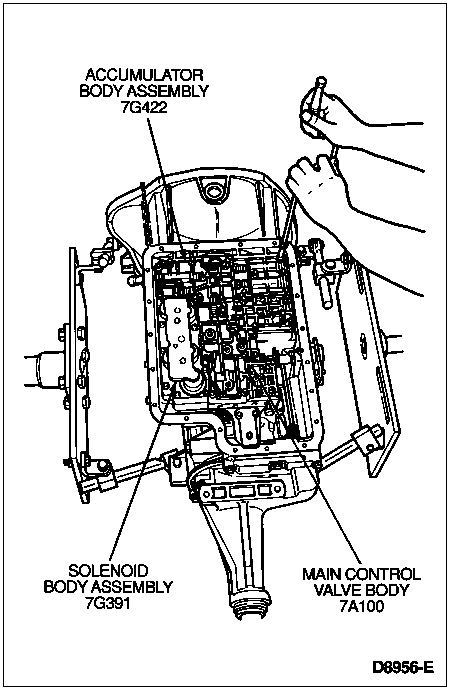
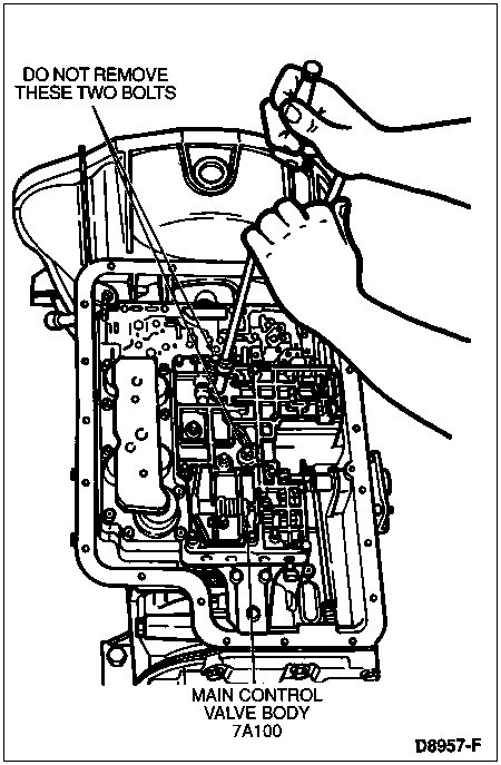
NOTE: Do not remove the two bolts shown. These two bolts hold the upper and lower main control valve bodies (7A100) together as an assembly.
Remove 14 main control valve body bolts using an 8 mm socket. Remove two nuts using a 10 mm socket. Remove main control valve body.
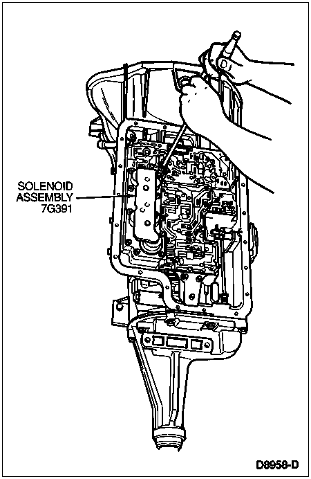
Remove nine solenoid body assembly bolts using a T30 Torx® bit and one nut using a 10 mm socket.
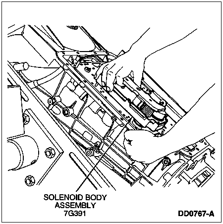
Push up on solenoid body assembly connector while removing solenoid body assembly.
Remove solenoid screen assembly by rotating and pulling out.

NOTE: Steel EPC check ball is spring loaded under valve body separator plate (7A008).
Remove three separator plate reinforcing plate bolts using an 8 mm socket. Remove separator plate reinforcing plate.
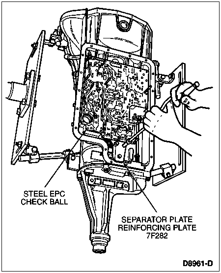
Remove valve body separator plate and two gaskets. Discard gaskets.
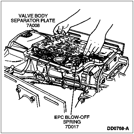
NOTE: The steel EPC check ball has 6.35-mm (0.25-inch) diameter and is smaller than the other check balls.
Remove steel EPC check ball and spring assembly.

![]() CAUTION: Use care not to damage rubber check balls.
CAUTION: Use care not to damage rubber check balls.
Remove eight rubber check balls from transmission, using a small screwdriver.
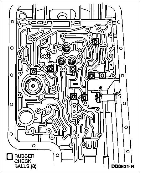
![]() WARNING: INTERMEDIATE BAND SERVO ASSEMBLY CAN COME APART AND POP OUT OF THE CASE BORE.
WARNING: INTERMEDIATE BAND SERVO ASSEMBLY CAN COME APART AND POP OUT OF THE CASE BORE.
![]() CAUTION: Tap gently on intermediate band servo assembly piston.
CAUTION: Tap gently on intermediate band servo assembly piston.
Using a plastic- or rubber-headed hammer, tap gently on the intermediate band servo assembly piston. The downward force will compress the spring. The upward momentum of the spring will force the assembly to be released from the case bore.

![]() CAUTION: Discard feedbolts after removal.
CAUTION: Discard feedbolts after removal.
Remove three feedbolts using a 13 mm socket. Discard feedbolts.
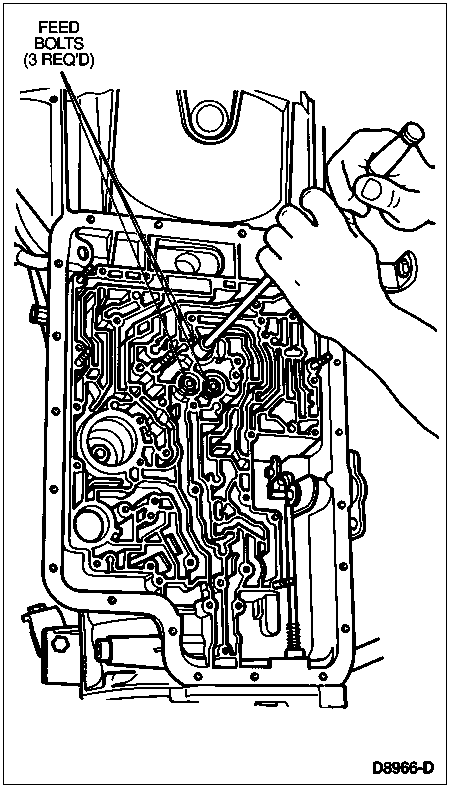
![]() CAUTION: Discard pump bolt washers after removal. Do not reuse.
CAUTION: Discard pump bolt washers after removal. Do not reuse.
Remove nine pump bolts using a 10 mm socket.
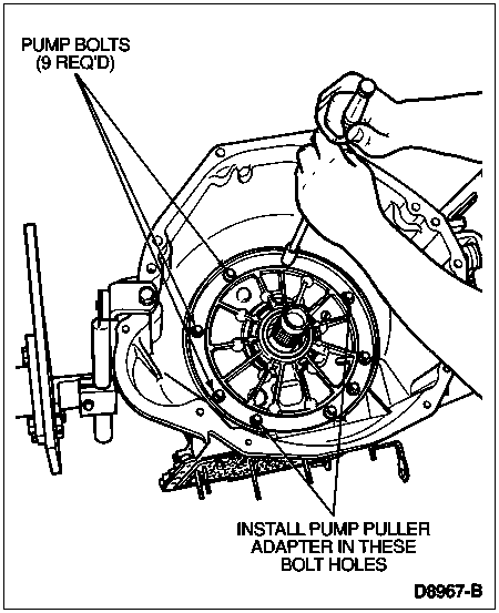
Use two threaded holes in pump and install Pump Puller Adapter T89T-70010-A. Install Impact Slide Hammer T59L-100-B into adapter and remove front pump assembly. Use slide hammer-type puller only.
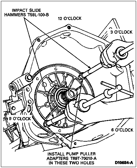
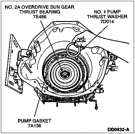
NOTE: No. 1 pump thrust washer and No. 2A overdrive sun gear thrust bearing may stay with pump.
Remove pump gasket and No. 1 pump thrust washer. Discard pump gasket. Remove No. 2A overdrive sun gear thrust bearing between front pump assembly and overdrive sun gear (7D063).
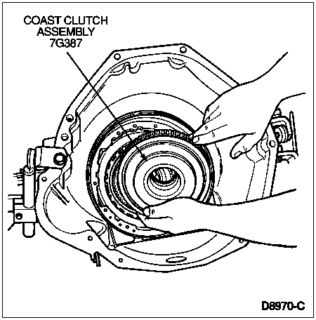
NOTE: Overdrive sun gear might stay with coast clutch or overdrive planet assembly.
Lift out the coast clutch assembly.
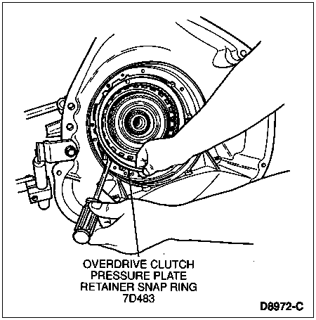
Remove overdrive clutch pressure plate retainer snap ring using large screwdriver.
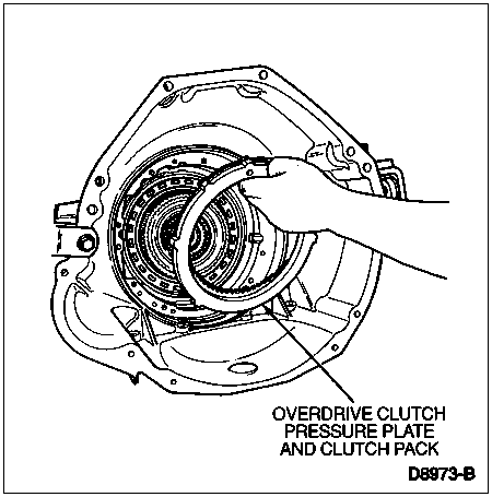
Remove overdrive clutch pressure plate and clutch pack and tag for reassembly.
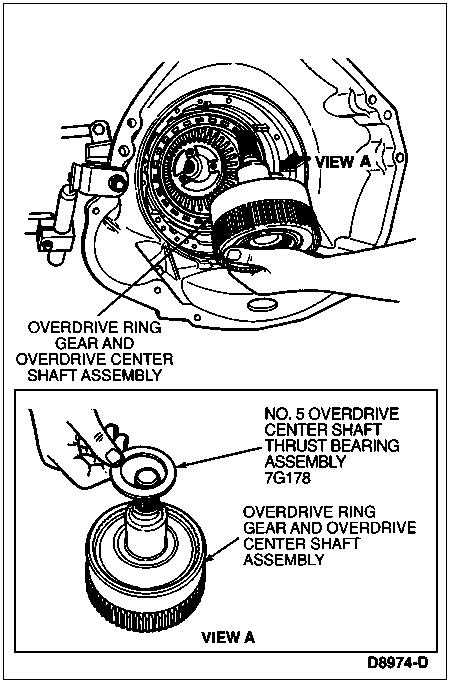
Remove overdrive ring gear and overdrive center shaft assembly, overdrive planet and one-way clutch and No. 5 overdrive center shaft thrust bearing assembly.
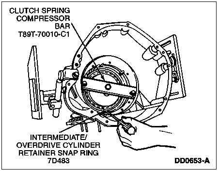
Install Clutch Spring Fixture T89T-70010-C onto intermediate/overdrive cylinder assembly. Tighten center bolt to 7 Nm (65 lb-in).

Remove intermediate/overdrive cylinder retainer snap ring with large screwdriver. Loosen spring compressor center bolt and remove compressor tools.
![]() CAUTION: During removal, do not misalign the intermediate/overdrive cylinder assembly in the case bore. This can damage the case bore.
CAUTION: During removal, do not misalign the intermediate/overdrive cylinder assembly in the case bore. This can damage the case bore.
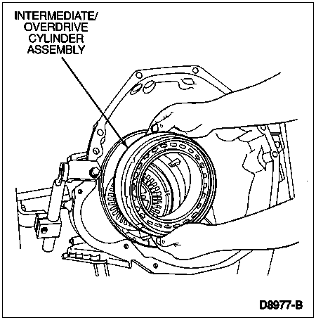
Remove intermediate/overdrive cylinder assembly.
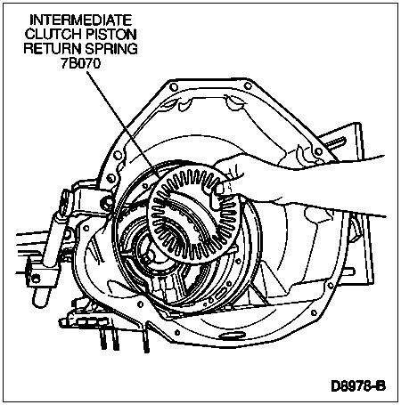
Remove intermediate clutch piston return spring.
![]() CAUTION: During removal, do not misalign the center support in the case bore. This can cause damage to the case bore.
CAUTION: During removal, do not misalign the center support in the case bore. This can cause damage to the case bore.
Carefully remove center support assembly.

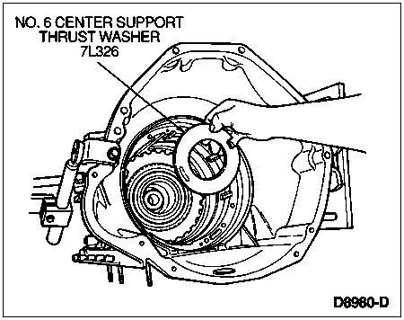
Remove No. 6 center support thrust washer (7L326).
Remove front intermediate clutch pressure apply plate, intermediate clutch pack and intermediate clutch rear pressure plate. Tag for proper reassembly.
Remove intermediate band.
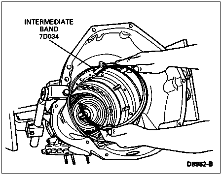
NOTE: When installing the special tool, the hooks on the crossbar must be rotated to engage notches on the input shell.
Using the special tool, remove the direct clutch, forward clutch and input shell as an assembly.

Using large screwdriver, remove reverse planet retaining ring.
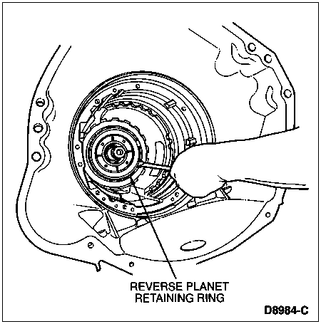
Remove reverse planet (7D006) assembly and No. 10B and No. 11 reverse planet carrier thrust washers.

![]() WARNING: USE CARE WHEN REMOVING THE OUTPUT SHAFT RETAINING RING. THE OUTPUT SHAFT (7060) CAN FALL OUT. DO NOT REUSE THE OUTPUT SHAFT RETAINING RING.
WARNING: USE CARE WHEN REMOVING THE OUTPUT SHAFT RETAINING RING. THE OUTPUT SHAFT (7060) CAN FALL OUT. DO NOT REUSE THE OUTPUT SHAFT RETAINING RING.
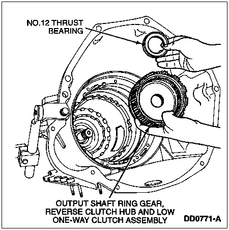
Using retaining ring pliers, remove the output shaft retaining ring.

Remove output shaft ring gear, reverse clutch hub, low one-way clutch assembly and No. 12 thrust bearing.
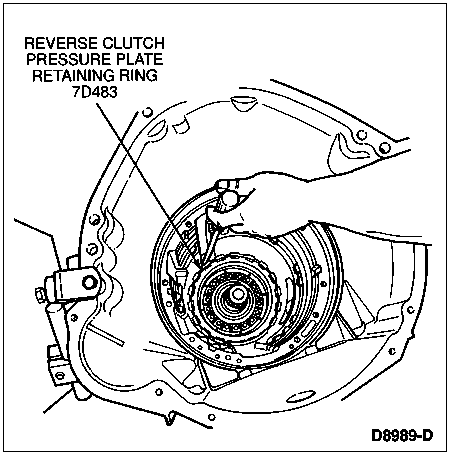
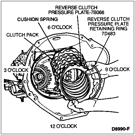
Using a large screwdriver remove reverse clutch pressure plate retaining ring.
![]() CAUTION: Use care not to drop output shaft while rotating transmission.
CAUTION: Use care not to drop output shaft while rotating transmission.
Rotate transmission so that transmission fluid pan rail surface is facing up.
Remove reverse clutch pressure plate and clutch pack and cushion spring. Tag for reassembly.
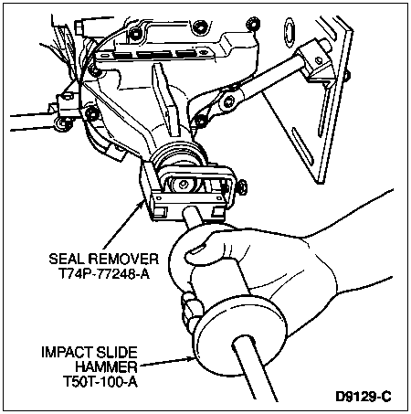
Using Seal Remover T74P-77248-A and Impact Slide Hammer T50T-100-A remove extension housing seal.
Remove nine extension housing bolts using a 13 mm socket. Remove wiring bracket, extension housing (7A039) and extension housing gasket.

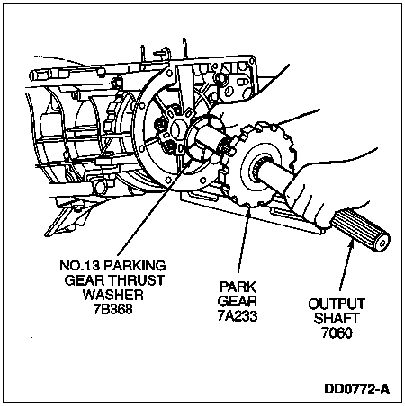
Remove output shaft, park gear (7A233) and No. 13 parking gear thrust washer.
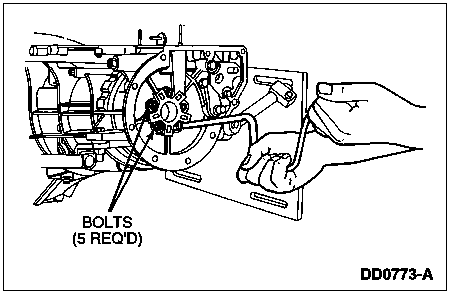
Using a 7/16-inch socket, remove five bolts retaining the low/reverse one-way clutch inner race to the case.
Remove reverse clutch return spring assembly and the low/reverse one-way clutch inner race.
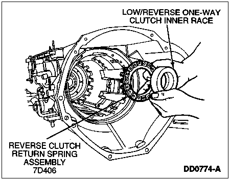
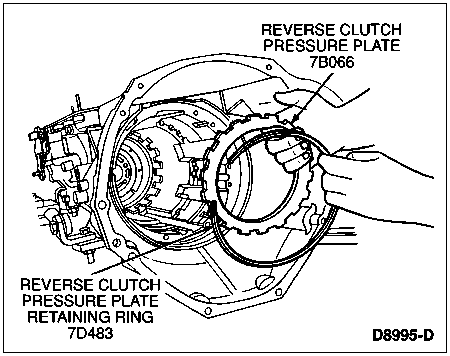
Reinstall reverse clutch pressure plate and reverse clutch pressure plate retaining ring to restrain the reverse clutch piston (7D402) during removal.
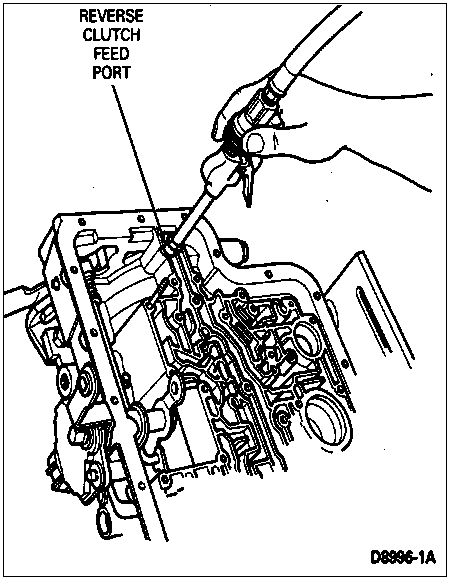
Blow into reverse clutch feed port using compressed air. This will blow out the reverse clutch piston against the reverse clutch pressure plate.
Remove reverse clutch pressure plate retaining ring, reverse clutch pressure plate and reverse clutch piston from case (7005).
Remove two parking rod guide plate bolts using 13 mm socket. Remove the parking rod guide plate.
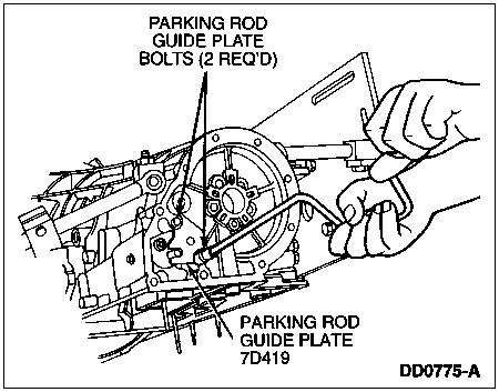
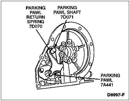
Remove parking pawl return spring (7D070), parking pawl (7A441) and parking pawl shaft (7D071) from case.
![]() CAUTION: The Torx® head screw has a thread-locking compound and should be removed only if the case is being replaced. If screw is removed, it must be discarded and a new one installed.
CAUTION: The Torx® head screw has a thread-locking compound and should be removed only if the case is being replaced. If screw is removed, it must be discarded and a new one installed.
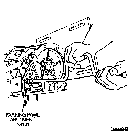
If required, remove the Torx® head screw using a T40 bit and remove parking pawl abutment.
NOTE: A Number 53 drill bit (1/16-inch) can be used as an alternate method to remove the manual lever shaft retaining pin (7B210).
Remove manual lever shaft retaining pin using Lock Nut Pin Remover T78P-3504-N.
Remove inner manual valve detent lever nut using a 21 mm box wrench while holding manual control lever (7A256) with a crescent wrench.
Remove inner manual valve detent lever (7A115) and parking pawl actuating rod from manual control lever shaft (7C493).
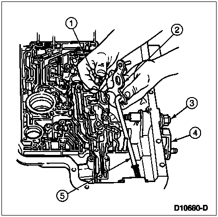
| Item | Part Number | Description |
|---|---|---|
| 1 | N800287-S36 | Inner Manual Valve Detent Lever Nut |
| 2 | 7A115 | Inner Manual Valve Detent Lever |
| 3 | N620482-S2 | Outer Manual Control Lever Nut |
| 4 | 7A256 | Outer Manual Control Lever |
| 5 | 7A232 | Parking Pawl Actuating Rod |
![]() CAUTION: Discard outer manual control lever shaft nut. Do not reuse.
CAUTION: Discard outer manual control lever shaft nut. Do not reuse.
Remove the outer manual control lever shaft nut using a 15 mm socket while holding outer manual control lever with crescent wrench.
Remove outer manual control lever.
Remove two transmission range (TR) sensor bolts and washers using an 8 mm socket and remove TR sensor.
![]() CAUTION: Use care not to damage the manual control lever bore.
CAUTION: Use care not to damage the manual control lever bore.
Remove manual control lever shaft.
Remove bolt and manual control valve detent lever spring (7A261).
Remove manual control lever seal using Puller T58L-101-B.

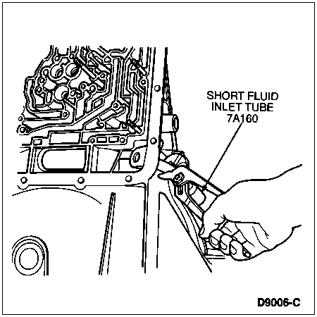
NOTE: Remove the short fluid inlet tube only if it is loose or damaged.
If necessary, remove short fluid inlet tube, using channel lock pliers.
