Section 13-01: Instrument Cluster, Conventional | 1996 F-150, F-250, F-350, Bronco, F-Super Duty Motorhome Chassis Workshop Manual |
![]() CAUTION: During in-vehicle tests, do not let tester terminal studs designated by arrows come in contact with vehicle ground. The gauge will be shorted to the ground, preventing an accurate test and possibly damaging the gauge.
CAUTION: During in-vehicle tests, do not let tester terminal studs designated by arrows come in contact with vehicle ground. The gauge will be shorted to the ground, preventing an accurate test and possibly damaging the gauge.
Disconnect connector from the appropriate sender and hook onto the matching terminals on the tester.
Turn the vehicle ignition switch lock cylinder (11582) to ON position.
Fuel Gauge, F-150, F-250, F-350
If only the fuel gauge is inoperative or appears to be out of calibration, a calibration test can be conducted on the vehicle fuel gauge system.
Fuel Tank Sending Unit
With the sending unit float arm in the empty stop position, resistance should be 15 ohms (below E). With the sending unit float arm in the full stop position, resistance should be 160 ohms (above F). The fuel gauge should read empty at 22.5 ohms and full at 145 ohms.
Fuel Tank Second Sending Unit Test, F-Series Dual Tanks
On F-Series aft/axle (standard) fuel tank (9002), the fuel sender electrical connector can be disconnected and attached to a second test sender outside the fuel tank. The float can then be manually operated (up and down) while the fuel gauge operation is observed. Proper gauge function indicates a problem with the fuel tank sending unit located in the fuel tank. Improper operation indicates a problem with the fuel tank gauge or wiring. Refer to Pinpoint Test A in this section.
Fuel Tank Damage
If fuel indicating system components are functioning properly and
inaccurate indications continue, check the fuel tank for damage which may have
changed the fuel tank sending unit mounting angle and/or damaged the fuel tank
sending unit. Make sure the fuel delivery module (FDM) is the correct model
for the vehicle and that the FDM is not contacting the bottom of the fuel
tank. Also inspect the vent hoses for kinks or obstructions.

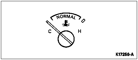
Coolant Temperature Gauge
Check gauge calibration as follows:

Oil Pressure Sender
Check gauge operation as follows:
Battery Voltage Gauge
Test the battery voltage gauge as follows:
Charge Indicator Lamp System
Normal Charge Indicator
With key off, charge indicator (battery symbol) lamp is off.
With key in RUN (engine (6007) not running), charge indicator (battery symbol) lamp is on.
With key in RUN (engine running), charge indicator (battery symbol) lamp is off.
If the charge indicator lamp does not light with the key in the RUN position (engine not running), check the I wiring circuit (ignition switch to regulator I terminal), for an open circuit or burned out charge indicator lamp.
If the charge indicator lamp does not light, disconnect the wiring plug connector at the regulator and connect a jumper wire from the I terminal of the regulator wiring plug to the negative battery post cable clamp.
The charge indicator lamp should light when the key is turned to RUN (engine not running).
If the charge indicator bulb does not light, check the bulb for continuity and replace if necessary.
If the bulb is not burned out, an open circuit exists between the ignition switch (11572) and the voltage regulator.
Check the 500-ohm resistor across the charge indicator lamp.
For additional diagnosis and testing procedures, refer to Section 14-00.