Fuel Level Indication System, Gasoline Engine

Section 13-01: Instrument Cluster, Conventional | 1996 F-150, F-250, F-350, Bronco, F-Super Duty Motorhome Chassis Workshop Manual |
The fuel level indicating system is a magnetic gauge system. It consists of a magnetic fuel gauge mounted in the instrument cluster (10849) and a fuel tank sending unit located in the fuel tank (9002).
Fuel Level Indication System, Gasoline Engine
| Item | Part Number | Description |
|---|---|---|
| 1 | Ś | Wiring Harness Connector (Part of 9275) |
| 2 | Ś | Fuel Supply Tube (Part of 9275) |
| 3 | Ś | Fuel Return Tube (Part of 9275) |
| 4 | Ś | Support Rod (Part of 9275) |
| 5 | 9002 | Fuel Tank |
| 6 | Ś | Fuel Delivery Module (Part of 9002) |
| 7 | Ś | Venturi Filter Screen (Part of 9002) |
| 8 | Ś | Sender Float Arm (Part of 9275) |
| 9 | Ś | Sender Float (Part of 9275) |
| 10 | Ś | Resistor Assembly (Part of 9275) |
| 11 | Ś | High-Pressure Pump Wiring (Part of 9002) |
| 12 | 10883 | Fuel Gauge |
Fuel Gauge
The magnetic gauge movement consists of three primary coils, one of which is wound at a 90-degree angle to the other two. The coils form a magnetic field that varies in direction according to the variable resistance of the sender unit that is connected between two of them. A primary magnet, to which a shaft and pointer are attached, rotates to align to this primary field, resulting in pointer position. The bobbin/coil assembly is pressed into a metal housing that has two holes for dial mounting. There is no adjustment, calibration or maintenance required for this gauge.
Fuel Sending Unit
The fuel tank sending unit consists of a variable screened resistor made up of a ceramic substrate. It is controlled by the action of an attached float in the fuel tank. When the fuel level is low, resistance in the fuel tank sending unit is low. When the fuel level is high, the resistance in the fuel tank sending unit is high. As the float moves from empty to full, the resistance will gradually and continuously increase.
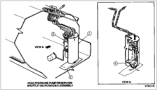
The electric fuel delivery system is used on the 4.9L SFI, 5.0L, 5.8L, and 7.5L multiport fuel injection (MFI) engines and utilizes a fuel delivery module (FDM) assembly. The FDM unit includes a high-pressure fuel pump, venturi jet pump, supply check valve, and a shuttle selector valve all located internally in the module, which acts as a reservoir mounted from the fuel tank sending unit flange. The fuel tank sending unit attached to the reservoir body is a separately serviceable component.
In addition, the FDM system achieves a significant reduction in fuel system complexity and simplifies fuel line routing. The in-line fuel filter is located on the left-hand frame rail to provide service access.
The fuel level sensor (9275) for the 7.3L diesel engine operates the same as that described for the MFI engines, except for the following differences:
The fuel tank sending units used with all engines have a fuel return port that allows excess fuel delivered to the engine to be returned to the fuel tank.
Fuel Level Sensor, Diesel Engine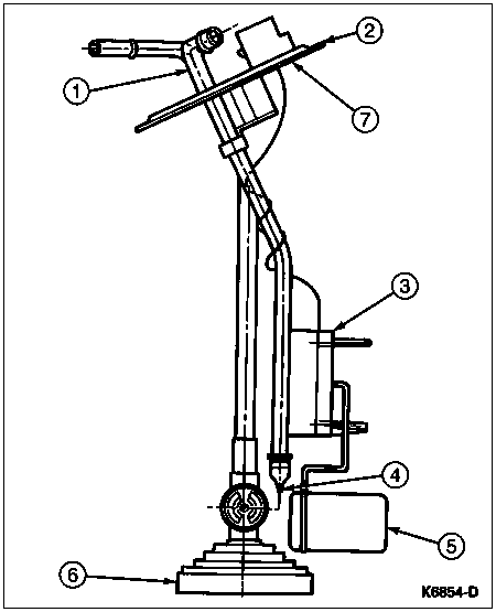
| Item | Part Number | Description |
|---|---|---|
| 1 | Ś | Fuel Line Assembly (Part of 9275) |
| 2 | 9275 | Fuel Level Sensor |
| 3 | Ś | Variable Resistor (Part of 9275) |
| 4 | Ś | Nipple (Part of 9275) |
| 5 | Ś | Float (Part of 9275) |
| 6 | Ś | Filter Assembly (Part of 9275) |
| 7 | Ś | Surface B (Part of 9275) |
| Item | Part Number | Description |
|---|---|---|
| 1 | Ś | Fuel Delivery Module (Part of 9H307) |
| 2 | Ś | In-Tank Venturi Filter (Part of 9H307) |
| 3 | 9A299 | Resistor Assembly |
| 4 | Ś | High-Pressure Pump (Part of 9H307) |
Fuel Tank Selector Switch
All fuel gauge sensing on vehicles with dual fuel tanks (except with 7.3L diesel engine (6007)) passes through the fuel tank selector switch. Refer to Diagnosis and Testing in this section for electrical schematics.