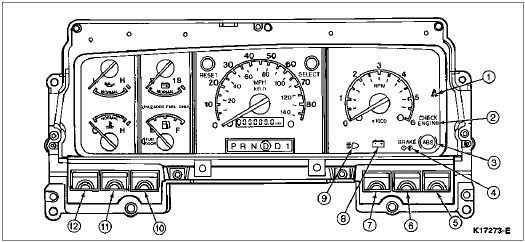
Base Cluster, F-150, F-250, F-350, F-Super Duty and Bronco

Section 13-01: Instrument Cluster, Conventional | 1996 F-150, F-250, F-350, Bronco, F-Super Duty Motorhome Chassis Workshop Manual |
The cluster warning lamps are located in two vertical columns, one on each side of the instrument cluster (10849) and also along the bottom of the instrument cluster. F-Series and Bronco optional instrument clusters have the warning lights along the right-hand side and bottom of the instrument cluster.
Base Cluster, F-150, F-250, F-350, F-Super Duty and Bronco

| Item | Part Number | Description |
|---|---|---|
| 1 | — | Fasten Seat Belt Indicator (Part of 10849) |
| 2 | — | High Beam Indicator (Part of 10849) |
| 3 | — | Charging System Indicator (Part of 10849) |
| 4 | — | Turn Signal Indicator (Part of 10849) (RH) |
| 5 | — | 4x4 High Range (Part of 10849) |
| 6 | — | Low Range Indicator (Part of 10849) |
| 7 | — | Air Bag Indicator (Part of 10849) |
| 8 | — | Not Used |
| 9 | — | Turn Signal Indicator (Part of 10849) (LH) |
| 10 | — | Brake Indicator (Part of 10849) |
| 11 | — | ABS Indicator (Part of 10849) |
| 12 | — | Check Engine Indicator (Part of 10849) |

| Item | Part Number | Description |
|---|---|---|
| 1 | — | Fasten Seat Belt Indicator (Part of 10849) |
| 2 | — | Check Engine Indicator (Part of 10849) |
| 3 | — | ABS Indicator (Part of 10849) |
| 4 | — | Brake Indicator (Part of 10849) |
| 5 | — | Turn Signal Indicator (Part of 10849) (RH) |
| 6 | — | 4x4 High Range (4-Wheel Drive Only) |
| 7 | — | Low Range (4-Wheel Drive Only) |
| 8 | — | Charging System Indicator (Part of 10849) |
| 9 | — | High Beam Indicator (Part of 10849) |
| 10 | — | Air Bag |
| 11 | — | Not Used |
| 12 | — | Turn Signal Indicator (Part of 10849) (LH) |
Instrument Cluster Display Proveout
When the key is turned to RUN, the following warning lamps will prove out by momentarily lighting.
Printed Circuit
The instrument cluster printed circuit (10K843), which supplies current to the instrument panel indicators, gauges, and some clocks, is made of copper foil that is bonded to a polyester base film (usually referred to as Mylar®).
The instrument cluster printed circuit is mounted to the cluster housing and, due to its location, cannot be easily inspected or tested in the vehicle. This makes the instrument cluster printed circuit vulnerable to damage when a probe is used for in-vehicle testing as the probe can pierce the instrument cluster printed circuit or, in some cases, burn the copper conductor.
Since there is no approved procedure for in-vehicle testing of the instrument cluster printed circuit, it must be removed for visual inspection. If no visual damage is evident, each circuit should be tested with an ohmmeter. If an open circuit or short is detected, the instrument cluster printed circuit must be replaced.