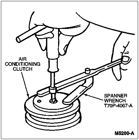
Hold clutch plate stationary and remove hex nut.
Section 12-03C: Compressor and Clutch, SD-7H15 | 1996 F-Super Duty Motorhome Chassis Cab Workshop Manual |
A/C Clutch and A/C Clutch Pulley
| Description | Tool Number |
|---|---|
| Spanner Wrench | T70P-4067-A |
| Steering Wheel Puller | T67L-3600-A |
Removal
Install Spanner Wrench T70P-4067-A into two threaded holes in the clutch front plate.
Hold clutch plate stationary and remove hex nut.

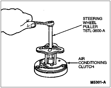
Using Steering Wheel Puller T67L-3600-A, align puller center bolt to compressor shaft. Tighten three puller bolts into the threaded holes, then screw puller center bolt down against A/C compressor center shaft until A/C clutch (2884) releases from the A/C compressor shaft.
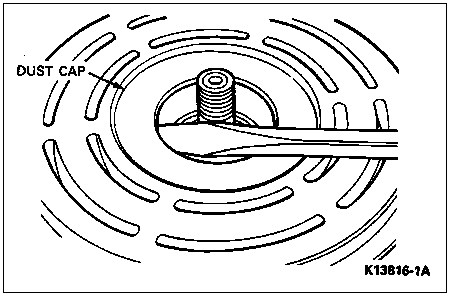
Remove bearing dust cover using a screwdriver.
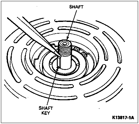
Remove shaft key by lightly tapping it loose with a slotted screwdriver and hammer.
Remove the internal bearing snap ring.

Remove the external front housing snap ring.
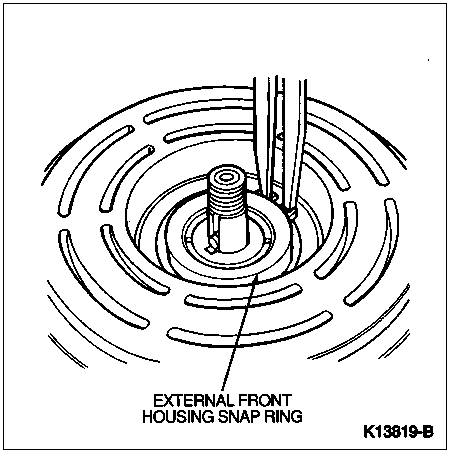
Insert puller jaws into the snap ring groove.
Place rotor puller shaft protector over exposed shaft.
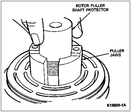
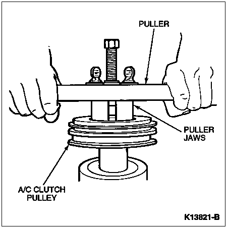
Align thumb head bolts to puller jaws and finger-tighten.
Tighten center bolt until A/C clutch pulley (2E884) is removed.
Installation
Support the A/C compressor (19703) on the four mounting ears on the rear of the compressor. If using a vise, clamp only on mounting ears, not on compressor body.
Align A/C clutch pulley squarely on the front housing hub.
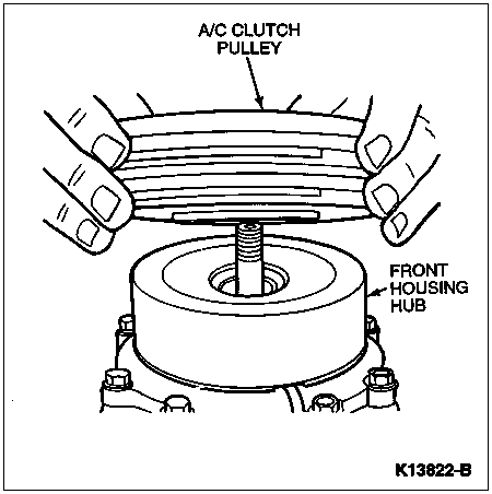
Using rotor installer ring set, place rotor installer ring into bearing cavity. Make sure the outer edge rests firmly on the A/C clutch pulley bearing outer race.
Place rotor installer driver into rotor installer ring.
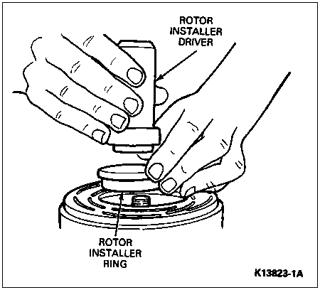
Tap driver with a hammer while guiding the A/C clutch pulley to prevent binding. Tap until the A/C clutch pulley bottoms against the compressor front housing hub.
Install internal bearing snap ring.
Install external front housing snap ring.
Install front plate assembly.
Install compressor shaft key.
Align front plate keyway to compressor shaft key.
Using shaft protector, tap front plate to shaft until it bottoms out on the shims.
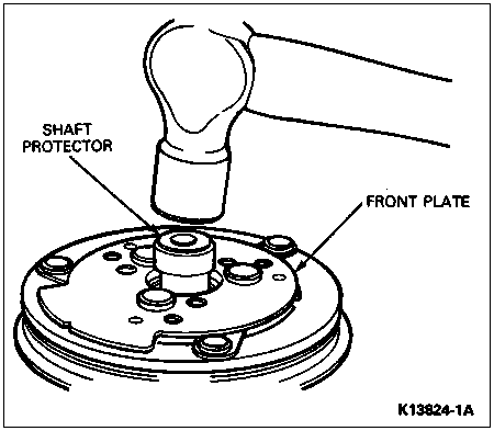
Install shaft hex nut. Tighten to 34-40 Nm (25-30 lb-ft).
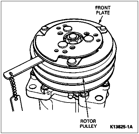
Check air gap using a 0.4-0.8mm (.016- to .031-inch) feeler gauge between hub and mating pulley surface in three locations equally spaced around pulley. Record air gap readings.
Rotate A/C clutch pulley one-half turn (180 degrees) and again check air gap in three equally spaced locations. Smallest air gap must be within specified limits for air gap. Add or remove shims between hub and compressor shaft end as necessary until smallest air gap is within specification.
A/C Clutch Field Coil
Removal
Remove A/C clutch hub and A/C clutch pulley.
Loosen coil lead wire clip from compressor front housing.
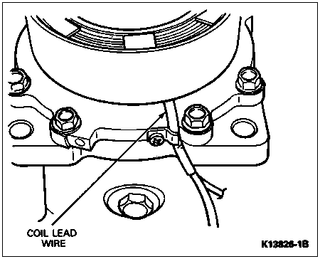
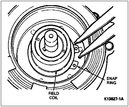
Remove snap ring and field coil.
Installation
Install A/C clutch field coil (2987) and snap ring.
Tighten clip on field coil lead wire.
Install A/C clutch pulley and hub on A/C compressor.