Airflow Through Duct System

Section 12-03A: Air Conditioning System, Manual A/C-Heater | 1996 F-150, F-250, F-350, F-Super Duty and Bronco, F-Super Duty Motorhome Chassis Workshop Manual |
The A/C control (19980) is installed in the center of the instrument panel (04320).
It includes the control assembly with one knob-operated A/C temperature cable (19988) for selecting temperature. A second knob moves a selector valve that activates the various function doors and air conditioner electrical contacts. A third knob moves electrical switch contacts so that they establish continuity for one of four available positions between LOW and HIGH speed of the blower.
Air can be distributed through the instrument panel registers, the heater outlet floor ducts (18C433), and the windshield defroster hose nozzles (18490) depending upon the position of the function selector knob. Airflow to the side window demisters occurs in all knob settings.
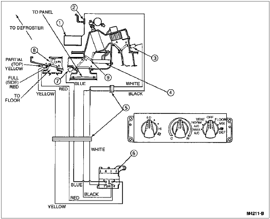
The following chart and illustration show the vacuum system and how it controls the three airflow doors:
| Port | Function | Max A/C | Norm A/C | Vent | Off | Floor | Mix | Def. |
|---|---|---|---|---|---|---|---|---|
| 1 (White) | Recirc. — O/S Air | V | A | A | V | A | A | A |
| 2 (Red) | Full Floor | V | V | V | V | V | A | A |
| 3 (Yellow) | Panel | V | V | V | V | V | V | A |
| 4 (Blue) | Mix | V | V | V | A | A | A | A |
| 5 (Black) | Source | V | V | V | V | V | V | V |
V = Vacuum
A = Atmosphere

| Item | Part Number | Description |
|---|---|---|
| 1 | 19A566 | A/C Vacuum Reservoir Tank and Bracket |
| 2 | 19A563 | A/C Vacuum Check Valve |
| 3 | — | Outside-Recirculation Door (White) (Part of Vacuum Harness) |
| 4 | 18476 | Heater Core |
| 5 | — | Vacuum Harness Connector (Part of Vacuum Harness) |
| 6 | 19980 | A/C Control |
| 7 | — | Panel Door (Blue) (Part of Vacuum Harness) |
| 8 | — | Floor Defrost Door (Part of 18471) |
| 9 | — | Temperature Blend Door (Part of 18471) |
Airflow Control
When the function selector knob (18519) is in the A/C (MAX and NORM) and VENT positions, air flows out of the panel registers. Moving the function knob to the FLOOR position directs airflow to the heater outlet floor ducts with a slight bleed to the windshield defroster hose nozzles. The MIX position splits the air between the heater outlet floor ducts and the windshield defroster hose nozzles, and DEFROST position directs airflow to the windshield defroster hose nozzles with a slight bleed to the heater outlet floor ducts.
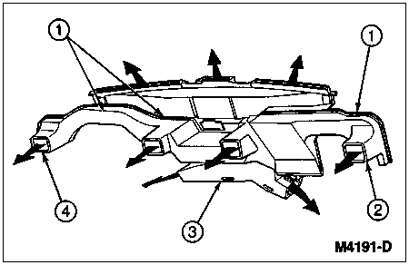
Airflow Through Duct System
| Item | Part Number | Description |
|---|---|---|
| 1 | 19E726 | A/C Instrument Panel Duct and Support |
| 2 | 04320 | Instrument Panel |
| 3 | 18C433 | Heater Outlet Floor Duct |
| 4 | — | Instrument Panel Ducts (Part of 19E726) |
The function knob actuates a vacuum selector valve that controls the movement of the door.
In the NORM A/C, VENT, FLOOR, MIX and DEFROST positions, outside air is drawn into the system by the blower motor (18527). In the OFF and MAX A/C positions, the recirculation door is positioned so that outside air cannot pass into the A/C evaporator case (19897). In the case of MAX A/C, passenger compartment air is recirculated. In OFF position, blower motor does not operate.
Temperature Control
Temperature is controlled by a manually operated air blend door in the heater air plenum chamber (18471). When the temperature control knob is in the extreme COOL position (fully counterclockwise) all air bypasses the heater core (18476).
When the temperature control knob is moved to the extreme WARM (fully clockwise) position, all air is directed through the heater core. When the temperature control knob is between COOL and WARM (between full counterclockwise and clockwise), air is directed through and bypassing the heater core in rough proportion to the position of the temperature control knob between the extremes of its travel.
Blower Motor Control
Speed is controlled by a four-position heater blower motor switch (18578) and a heater blower motor switch resistor (18591) located in the A/C evaporator case upstream from the A/C evaporator core (19860).
The switch is used to select LOW, two intermediate, and HIGH speed settings. The heater blower motor switch is turned off by rotating the function selector knob to its OFF position.
A/C Switch
The air conditioning system is turned on and off by the function selector switch. When the function selector knob is positioned in any A/C mode (MAX or NORM), and the engine is running, electrical current flows through the A/C cycling switch (19E561) to the A/C clutch field coil (2987), the A/C clutch (2884) engages and the air conditioning system operates (providing ambient air temperatures are above a prescribed temperature). When the function selector knob is set in the DEFROST or MIX positions and the same above conditions are met, the A/C system will also operate. This allows the operator to select the proper air temperature (when the temperature control is adjusted) for defogging the windshield and side glass when necessary, by taking advantage of the dehumidification benefits of the air conditioning system. When the function selector is placed in any other position, current is stopped to the air conditioning circuit and the A/C compressor (19703) ceases operation.