Section 12-02: Heating and Defrosting | 1996 F-150, F-250, F-350, F-Super Duty and Bronco, F-Super Duty Motorhome Chassis Workshop Manual |
Removal
Remove the instrument panel center finish panel. Refer to Section 01-12.
Disconnect the battery ground cable(s).
Remove the heater control (18549) from the instrument panel (04320) as described previously. Do not detach cable or harnesses.
Remove the knob (18519) from the heater blower motor switch (18578) by pulling on the knob.
Pull heater control through opening far enough to allow removal of electrical connector.
Remove electrical connector from heater blower motor switch by lifting snap-lock retainer with a screwdriver and pulling on the connector.
Remove the attaching screw and rotate the heater blower motor switch counterclockwise to release it from the retaining tabs.
Installation
Insert the shaft without its knob through the opening in the heater control.
Rotate the heater blower motor switch clockwise to engage it with the retaining tabs. Install the attaching screw.
Install the knob.
Attach the electrical connector to the heater blower motor switch.
Position the heater control in its opening. Install its four attaching screws and install bezel.
Install the instrument panel finish panel. Refer to Section 01-12.
NOTE: When the battery (10655) has been disconnected and reconnected, some abnormal drive symptoms may occur while the powertrain control module (PCM) (12A650) relearns its adaptive strategy. The vehicle may need to be driven 16 km (10 miles) or more to relearn the strategy.
Connect the battery ground cable(s).
Check the heater blower motor switch for proper operation.
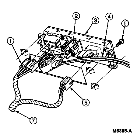
Item | Part Number | Description |
---|---|---|
1 | 14401 | Main Wiring (to Function Selector Switch) |
2 | 18C613 | Temperature Bracket Assembly |
3 | 18549 | Heater Control |
4 | 19988 | A/C Temperature Cable |
5 | N803877-S36B | Screw (4 Req'd) |
6 | 14401 | Main Wiring (to Blower Switch) |
7 | 14401 | Main Wiring |