Section 12-02: Heating and Defrosting | 1996 F-150, F-250, F-350, F-Super Duty and Bronco, F-Super Duty Motorhome Chassis Workshop Manual |
![]() WARNING: CARBON MONOXIDE IS COLORLESS, ODORLESS AND DANGEROUS. IF IT IS NECESSARY TO OPERATE THE ENGINE WITH THE VEHICLE IN A CLOSED AREA SUCH AS A GARAGE, ALWAYS USE AN EXHAUST COLLECTOR TO VENT THE EXHAUST GASES OUTSIDE THE CLOSED AREA.
WARNING: CARBON MONOXIDE IS COLORLESS, ODORLESS AND DANGEROUS. IF IT IS NECESSARY TO OPERATE THE ENGINE WITH THE VEHICLE IN A CLOSED AREA SUCH AS A GARAGE, ALWAYS USE AN EXHAUST COLLECTOR TO VENT THE EXHAUST GASES OUTSIDE THE CLOSED AREA.
![]() CAUTION: Whenever components in areas of the engine compartment or instrument panel (04320) are being serviced, the battery ground cable must be disconnected to eliminate the possibility of electrical shorts, burned-up wiring and fires. Extreme care must be exercised when performing electrical tests where the battery must be connected to operate the system.
CAUTION: Whenever components in areas of the engine compartment or instrument panel (04320) are being serviced, the battery ground cable must be disconnected to eliminate the possibility of electrical shorts, burned-up wiring and fires. Extreme care must be exercised when performing electrical tests where the battery must be connected to operate the system.
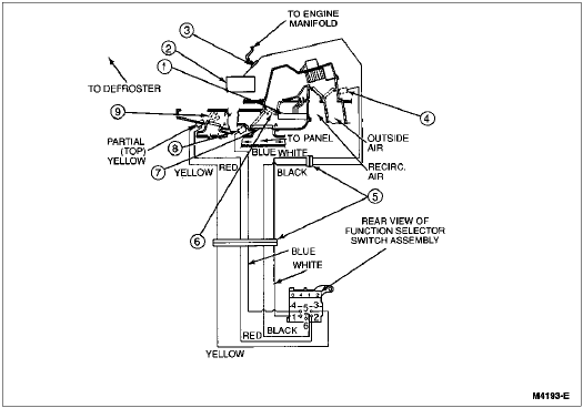
The following diagram illustrates the vacuum hose connections between the vacuum source, vacuum control motors (18A318), and A/C control (19980). The diagram also identifies the color coding of the vacuum hoses and charts the function control knob settings and vacuum application by heater control (18549) and function.
Function Control Vacuum Circuit
| Item | Part Number | Description |
|---|---|---|
| 1 | 18476 | Heater Core |
| 2 | 19A566 | A/C Vacuum Reservoir Tank and Bracket |
| 3 | 19A563 | A/C Vacuum Check Valve |
| 4 | — | Outside-Recirc. Door (White) (Part of Vacuum Harness) |
| 5 | — | Vacuum Harness Connector (Part of Vacuum Harness) |
| 6 | — | Temperature Blend Door (Cable Controlled) (Part of 18471) |
| 7 | — | Floor/Panel Door (Part of 18471) |
| 8 | — | Panel Vacuum Motor (Part of 18A318) |
| 9 | — | Floor/Defrost Door (Red/Yellow) (Part of 18471) |
| Tube Color | Port No. | Function/Door | Vent | Floor | Off | Mix | Def |
|---|---|---|---|---|---|---|---|
| White | 1 | Recirc. — O/S (Outside Air) | A | A | V | A | A |
| Red | 2 | Floor — Defrost (Side Port) | V | V | V | A | A |
| Yellow | 3 | Floor — Defrost (End Port) | V | V | V | V | A |
| Blue | 4 | Panel | V | A | A | A | A |
| Black | 5 | Source | V | V | V | V | V |
V = Vacuum.
A = Atmosphere.