Air Distribution

Section 12-02: Heating and Defrosting | 1996 F-150, F-250, F-350, F-Super Duty and Bronco, F-Super Duty Motorhome Chassis Workshop Manual |
The heater is a blend air type that receives its outside air supply from the cowl inlet. The heater control (18549) is located in the instrument panel (04320) to the right of the steering column. It includes the function control knob, temperature control knob and heater blower motor switch (18578).
The heater blower housing assembly includes:
The heater blower housing is installed on the engine compartment side of the dash panel. Electrical wire receptacles for the blower motor and heater blower motor switch resistor are provided on the heater plenum chamber case (18A484) and a vacuum connection is provided on each vacuum control motor.
A heater air plenum chamber (18471), on the passenger compartment side of the dash panel attaches to the heater plenum chamber case through the panel with an air passage between the assemblies provided through an opening in the panel.
The heater air plenum chamber includes the following components:
The vacuum control motors and their vacuum lines operate the floor/defrost and floor/panel doors. The temperature blend door is operated mechanically by a A/C temperature cable (19988) attached to the temperature control knob in the heater control.
The function control knob is used to select the functional setting of the heater system. The settings are: VENT, FLOOR, OFF, MIX and DEFROST. Power is supplied to the blower motor when the function knob is in any position except OFF.
Airflow Control
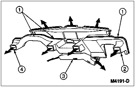
Outside air is supplied to the system through the cowl top grille. This air supply enters the heater plenum chamber case where the blower motor directs some or all air through or around the heater core depending upon the setting of the temperature control knob. Airflow through the heater air plenum chamber is determined by the setting of the function selector knob in the heater control. The outlets through which air may be distributed into the passenger compartment are shown in the following illustration.
Air Distribution
| Item | Part Number | Description |
|---|---|---|
| 1 | 19E726 | A/C Instrument Panel Duct and Support |
| 2 | 04320 | Instrument Panel |
| 3 | 18C433 | Heater Outlet Floor Duct |
| 4 | — | Instrument Panel Ducts (2) Driver's Side (Part of 19E726) |
Temperature Control
Depending upon its position, the temperature blend door in the heater air plenum chamber directs a given amount of air through the heater core to provide a desired amount of heat. If the amount of air directed by the blend door through the heater core is reduced, less heat will be directed into the passenger compartment.
Conversely, a fully open blend door, in response to a fully WARM setting of the temperature control knob, will provide maximum heat into the passenger compartment.
Blower Motor Control
Three of four operating speeds (LOW, MEDIUM LOW and MEDIUM HIGH) are controlled by a heater blower motor switch resistor connected in series with three of the operating positions and the ground. The MEDIUM LOW and MEDIUM HIGH positions on the heater control are identified by dots on the control.
With the heater blower motor switch in its LOW position, current flow in the ground circuit passes through three of the coils in the heater blower motor switch resistor. In MEDIUM LOW, current flows through two coils. In MEDIUM HIGH, current flows through one coil. In HIGH, current flow in the motor ground circuit bypasses the heater blower motor switch resistor to provide maximum speed.
Recirculation/Fresh Air Control
The vehicle heating system draws outside air into it and distributes this fresh air throughout the passenger compartment in all positions except OFF. If the vehicle is equipped with air conditioning, outside air is distributed throughout the vehicle in all positions except OFF and MAX A/C. In these positions (OFF, MAX A/C) the A/C fresh air inlet door is in the closed position and air within the passenger compartment is recirculated throughout.