Section 12-00: Climate Control System, Service
1996 F-150, F-250, F-350, F-Super Duty and Bronco, F-Super Duty Motorhome Chassis Workshop Manual
SERVICE PROCEDURES

A/C Evaporator Core and/or A/C Condenser Core


On-Vehicle Leak Test


Evaporator Core

  1. Verify that the manifold gauge set is capable of holding vacuum:

    1. Connect the RED and BLUE hoses together using a 1/4-inch flare coupling.
    1. Connect the gauge set YELLOW hose to a known good vacuum pump.
    1. Turn the vacuum pump ON and open both gauge set valves.
    1. Operate the vacuum pump for one minute and close both gauge set valves. The low side gauge should indicate approximately 30 inches of vacuum.
    1. Allow the gauge set, with vacuum applied, to set for at least one-half hour.
    1. If the gauge reading drops during that time, the gauge set hose connections, gauges, or valves are leaking and should be repaired before proceeding with the leak test.
  1. Discharge the A/C system using the procedure outlined in System Evacuating in the Service Procedures portion of this section.

  1. Disconnect the liquid line and suction accumulator from the evaporator core tubes. DO NOT leak test an evaporator core with the suction accumulator attached to the core tubes. Refrigerant outgassing from oil and desiccant in the accumulator will indicate a false leak condition.

  1. Clean the evaporator core tube fittings.

    For threaded connections wipe any dirt or debris from sealing surfaces with a clean, lint-free rag.

    If the evaporator core tube fittings are the female spring lock design, check the inside of each fitting for scratches, corrosion, or debris from deteriorated O-rings. If scratches, corrosion, or debris are found, the leak test results may not be accurate unless the fitting is properly cleaned as follows:

    1. Remove any surface residue from the inside of the female spring lock coupling by polishing with 400 grit emery cloth (or equivalent). Polish the female surface by using a twisting motion so that any scratches made will not cross the O-ring sealing surface.
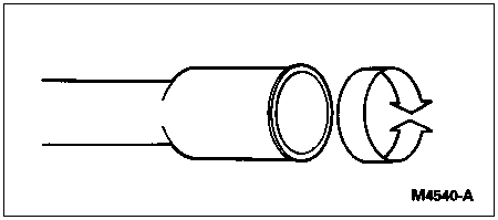


    1. Perform additional polishing of surface using 600 grit emery cloth (or equivalent).
    1. All residue from the polishing operations should be removed from the fitting by wiping with a lint-free rag.
  1. For this particular test procedure, it will be necessary to use a manifold gauge set for an R-12 refrigerant system, as the manifold gauge set for the R-134a refrigerant system cannot be attached to the leak test adapters.

    Connect the appropriate test fittings from Test Adapter Set D93L-19703-B to the evaporator tube connections.

  1. NOTE: The automatic shutoff valves on some gauge set hoses do not open when connected to the test fittings. If available, use hoses without shutoff valves. If hoses with shutoff valves are used, check to be sure the valve opens when attached to the test fittings or install an adapter that will activate the valve. The test is not valid if the shutoff valve does not open, only the hose will be tested.

    Connect the RED and BLUE hoses from the gauge and manifold set to the test fittings on the evaporator core. Connect the YELLOW hose to a known quality vacuum pump.

  1. Open both gauge set valves and start the vacuum pump. Turn the A/C system blower on low and allow the vacuum pump to operate for a minimum of 45 minutes after the gauge set low-pressure gauge indicates 101 kPa (30 in-Hg). The 45-minute evacuation is necessary to remove any refrigerant from oil left in the evaporator core. If the refrigerant is not completely removed from the oil, outgassing will occur and degrade the vacuum and appear as a refrigerant leak.

  1. If the low-pressure gauge reading will not drop to 101 kPa (30 in-Hg) when the valves on the gauge and manifold set are open and the vacuum pump is operating, close the gauge set valves and observe the low-pressure gauge. If the pressure rises rapidly to zero, a large leak is indicated. Recheck the test fitting connections and gauge set connections before replacing the A/C evaporator core (19860).

  1. If the low-pressure gauge reading rises 10 or more inches of vacuum from the 30 inch position in 10 minutes, a leak is indicated. If a loss of 3-10 inches of vacuum is observed in 10 minutes, wait 30 minutes to see if the gauge reading stabilizes. If the vacuum reading stabilizes, operate the vacuum pump for an additional 45 minutes with both gauge valves open to remove any remaining refrigerant from the A/C condenser core (19712) and recheck for loss of vacuum as outlined previously in this step.

    If a loss of 1-3 inches of vacuum occurs over 30 minutes, allow the system to sit overnight with system under vacuum and check for stabilization of the vacuum gauge reading. Stabilization of vacuum reading of 27-30 inches of vacuum indicates that the A/C condenser core does not leak. Always remember that a leaking fitting, manifold gauge set or hose connection will appear as a leaking A/C condenser core.

  1. If the A/C evaporator core does leak, as verified by the above procedure, install a new A/C evaporator core. Refer to Section 12-03A.


Condenser

  1. Verify that the manifold gauge set is capable of holding vacuum:

    1. Connect the RED and BLUE hoses together using a 1/4-inch flare coupling.
    1. Connect the gauge set YELLOW hose to a known good vacuum pump.
    1. Turn the vacuum pump ON and open both gauge set valves.
    1. Operate the vacuum pump for one minute and close both gauge set valves. The low side gauge should indicate approximately 30 inches of vacuum.
    1. Allow the gauge set, with vacuum applied, to set for at least one-half hour.
    1. If the gauge reading drops during that time, the gauge set hose connections, gauges, or valves are leaking and should be repaired before proceeding with the leak test.
  1. Discharge the A/C system. Refer to System Evacuating in the Service Procedures portion of this section.

  1. Disconnect the high-pressure line and discharge line at the condenser. Plug the lines leading to the A/C compressor (19703) and evaporator.

  1. Clean A/C condenser core fittings.

    For threaded connections wipe any dirt or debris from sealing surfaces with a clean, lint-free rag.

    If the tube fittings are the female spring lock design, check the inside of each fitting for scratches, corrosion, or debris from deteriorated O-rings. If scratches, corrosion, or debris are found, the leak test results may not be accurate unless the fitting is properly cleaned as follows.

    1. Remove any surface residue from the inside of the female spring lock coupling by polishing with 400 grit emery cloth (or equivalent). Polish the female surface by using a twisting motion so that any scratches made will not cross the O-ring sealing surface.


    1. Perform additional polishing of surface using 600 grit emery cloth or equivalent.
    1. All residue from the polishing operations should be removed from the fitting by wiping with a lint-free rag.
  1. For this particular test procedure, it will be necessary to use a manifold gauge set for an R-12 refrigerant system, as the manifold gauge set for the R-134a refrigerant system cannot be attached to the leak test adapters.

    Connect the appropriate test fittings from Test Adapter Set D93L-19703-B to the condenser tube connections.

  1. NOTE: The automatic shutoff valves on some gauge set hoses do not open when connected to the test fittings. If available, use hoses without shutoff valves. If hoses with shutoff valves are used, check to be sure the valve opens when attached to the test fittings or install an adapter which will activate the valve. The test is not valid if the shutoff valve does not open; only the hose will be tested.

    Connect the RED and BLUE hoses from the gauge and manifold set to the test fittings on the evaporator core. Connect the YELLOW hose to a known quality vacuum pump.

  1. Open both gauge set valves and start the vacuum pump. Turn the A/C system blower on low and allow the vacuum pump to operate for a minimum of one-half hour after the gauge set low-pressure gauge indicates 101 kPa (30 in-Hg). The one-half hour evacuation is necessary to remove any refrigerant from oil left in the A/C condenser core. If the refrigerant is not completely removed from the oil, outgassing will occur and degrade the vacuum and appear as a refrigerant leak.

  1. If the low-pressure gauge reading will not drop to 101 kPa (30 in-Hg) when the valves on the gauge and manifold set are open and the vacuum pump is operating, close the gauge set valves and observe the low-pressure gauge. If the pressure rises rapidly to zero, a large leak is indicated. Recheck the test fitting connections and gauge set connections before replacing the A/C condenser core.

  1. If the low-pressure gauge reading rises 10 or more inches of vacuum from the 101 kPa (30 in-Hg) position in ten minutes, a leak is indicated. If a very small leak is suspected, wait 30 minutes and observe the vacuum gauge. If a small amount of vacuum is lost, operate the vacuum pump with gauge valves open for an additional 30 minutes. Then, recheck for loss of vacuum as outlined. If a very small leak is suspected, allow the system to set overnight with vacuum applied and check for vacuum loss.

    A leaking fitting, gauge set or hose connection will appear as a leaking A/C condenser core.

  1. If the A/C condenser core does leak, as verified by the above procedure, install a new A/C condenser core. Refer to Section 12-03A.