Section 12-00: Climate Control System, Service | 1996 F-150, F-250, F-350, F-Super Duty and Bronco, F-Super Duty Motorhome Chassis Workshop Manual |
SERVICE PROCEDURES
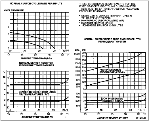
Refrigerant System Tests
Poor air conditioning system performance can be caused by an obstructed A/C evaporator core (19860). Airflow is restricted.
This condition can be detected by checking the center register discharge temperature. An abnormally low temperature indicates air is spending more time in the A/C evaporator core and is very cold when discharged, although the airflow volume is not enough to cool the vehicle properly.
Additional cause components are listed at the bottom of the chart for poor compressor operation or a damaged compressor condition.
These diagnosis charts provide the most direct and sure way to determine the cause of any problem in a poorly performing refrigerant system.
After servicing and correcting a refrigerant system concern, take additional pressure readings and observe the cycle rate while meeting the conditional requirements to be sure the concern has been corrected.
To diagnose a problem in the refrigerant system, note the system pressure (shown by the gauges) and the clutch cycle rate. Then compare readings with the charts.
To achieve accurate diagnosis results in the least amount of time use the following procedure and refer to the charts.
NOTE: The test conditions specified at the top of each of the charts must be met to obtain accurate test results.
Connect a gauge set to the system.
When system has stabilized, record high and low pressures as shown by gauges.
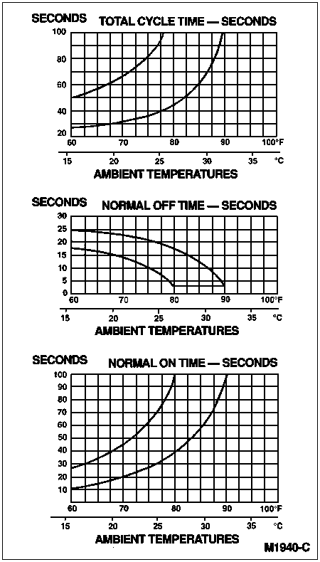
Determine cycle rate per minute (ON time plus OFF time is one cycle).
Record OFF time in seconds.
Record ON time in seconds.
Note center register discharge temperature.
Determine and record ambient temperature.
Compare test readings and appropriate chart.
- Plot a vertical line for recorded ambient temperature from scale at bottom of each chart to top of chart.
- Plot a horizontal line for other test readings from scale at left side of appropriate chart.
If the point where the two lines cross on each chart falls within the dark band, the system is operating normally. If the lines cross outside the dark band on one or more of the charts, there is a problem and the specific cause must be determined. Refer to the following System Pressure and Cycle Timing Evaluation Charts.
NOTE: The following five system operating conditions are indicated by where the lines cross on the chart:
- System high (discharge) — pressure is high, low or normal.
- System low (suction) — pressure is high, low or normal.
- Cycle rate is fast, slow or A/C clutch (2884) runs continuously.
- ON time is long or short.
- OFF time is long or short.
System Pressure and Cycle Timing Evaluation Charts
Match these conditions to the conditions shown in the five columns toward the left following Refrigerant System Pressure and Cycle Timing Evaluation Chart for A/C Evaporator Core Orifice Cycling Systems. All five system conditions will be indicated on one line. The most likely component or components causing the problem are listed in the right column.
Refrigerant System Pressure and Cycle Timing Evaluation Chartfor A/C Evaporator Core Orifice Cycling Systems
NOTE: Normal system conditional requirements must be maintained to properly evaluate refrigerant system pressures. Refer to charts applicable to system under test.
| High (Discharge) Pressure | Low (Suction) Pressure | Clutch Cycle Time | Component — Causes |
|---|
| Rate | On | Off |
|---|
| High | High | Continuous
Run | Continuous
Run | Continuous
Run | A/C Condenser Core — Inadequate Airflow. |
| High | Normal
to High | Continuous
Run | Continuous
Run | Continuous
Run | Engine Overheating. |
Normal
to High | Normal | Continuous
Run | Continuous
Run | Continuous
Run | Air in Refrigerant.
Refrigerant Overcharge.a
Humidity or Ambient Temperature Very High.b |
| Normal | High | Continuous
Run | Continuous
Run | Continuous
Run | A/C Evaporator Core Orifice — Missing.
O-Rings Leaking/Missing. |
| Normal | High | Slow | Long | Long | A/C Clutch Cycling Pressure Switch — High Cut-In. |
| Normal | Normal | Slow or
No Cycle | Long or
Continuous | Normal or
No Cycle | Moisture in Refrigerant System.
Excessive Refrigerant Oil. |
| Normal | Normal | Fast | Short | Short | A/C Clutch Cycling Pressure Switch —
Cut-In or High Cut-Out. |
| Normal | Low | Slow | Long | Long | A/C Clutch Cycling Pressure Switch — Low Cut-Out. |
Normal
to Low | High | Continuous
Run | Continuous
Run | Continuous
Run | Compressor — Low Performance. |
Normal
to Low | Normal
to High | Continuous
Run | Continuous
Run | Continuous
Run | Evaporator to Compressor Suction Line —
Partially Restricted or Plugged.c |
Normal
to Low | Normal | Fast | Short | Normal | Evaporator — Low Airflow. |
Normal
to Low | Normal | Fast | Short to
Very Short | Normal
to Long | A/C Condenser Core, A/C Evaporator Core Orifice, or Dryer to Evaporator Liquid Line — Partially Restricted or Plugged. |
Normal
to Low | Normal | Fast | Short to
Very Short | Short to
Very Short | Low Refrigerant Charge. |
Normal
to Low | Normal | Fast | Short to
Very Short | Long | Evaporator Core — Partially Restricted or Plugged. |
Normal
to Low | Low | Continuous
Run | Continuous
Run | Continuous
Run | Evaporator to Compressor Suction Line —
Partially Restricted or Plugged.d
A/C Clutch Cycling Switch — Sticking Closed. |
| Low | Normal | Very Fast | Very Short | Very Short | A/C Clutch Cycling Switch — Cycling Range Too Close. |
Erratic
Operation or
Compressor
Not Running | Erratic
Operation or
Compressor
Not Running | — | — | — | A/C Clutch Cycling Switch — Dirty Contacts or Sticking Open.
Poor Connection at A/C Clutch Connector or A/C Clutch Cycling Pressure Switch Connector.
A/C Electrical Circuit Erratic — See A/C Electrical Circuit Wiring Diagram. |
| Additional Possible Cause Components Associated with Inadequate A/C Compressor Operation |
A/C
Compressor
Drive Belt | — | — | — | — | A/C Compressor Drive Belt Loose. |
A/C
Clutch | — | — | — | — | A/C Clutch Slipping. |
A/C
Compressor
Clutch Field
Coil | — | — | — | — | A/C Compressor Clutch Field Coil Open — Shorted, or Loose Mounting. |
A/C Control
Assembly
Switch | — | — | — | — | Control Assembly Switch — Dirty Contacts or Sticking Open. |
A/C Clutch
Wiring Circuit | — | — | — | — | A/C Clutch Wiring Circuit — High Resistance, Open or Blown Fuse. |
| Additional Possible Cause Components Associated with a Damaged Compressor |
A/C Cycling
Switch | — | — | — | — | A/C Cycling Switch — Sticking Closed or A/C Clutch Seized. |
A/C Suction
Accumulator
Drier | — | — | — | — | A/C Suction Accumulator Drier — Refrigerant Oil Bleed Hole Plugged. |
| Refrigerant Low | — | — | — | — | Refrigerant Leaks. |
a Compressor may make noise on initial run. This is slugging condition caused by excessive liquid refrigerant.
b A/C compressor clutch may not cycle in ambient temperatures above 80°F depending on humidity conditions.
c Low pressure reading will be
normal to high if pressure is taken at accumulator and if restriction is downstream of service access valve.
d Low pressure reading will be
low if pressure is taken near the compressor and restriction is upstream of service access valve.
Service Access Gauge Port Valves
 WARNING: BEFORE ANY SERVICING OF THE A/C SERVICE GAUGE PORT VALVES CAN BE PERFORMED, THE REFRIGERANT SYSTEM MUST BE DISCHARGED. REFER TO REFRIGERANT RECOVERY IN THE SERVICE PROCEDURES PORTION OF THIS SECTION.
NOTE: The A/C service port valves are of the one-piece design. The top portion of the fitting is aluminum and is threaded into a steel body on the suction accumulator/drier (19C836) or on a refrigerant line and sealed with an O-ring seal. The valve seal is an integral part of the aluminum fitting piece that must be replaced if the seal leaks. Two special service tools have been developed to aid in the servicing of the service access gauge port valves. They are High Side A/C Fitting Socket D94L-19703-A or equivalent and Low Side A/C Fitting Socket D94L-19703-B or equivalent. The Schrader valve core used on R-12 systems is NOT used. The high side fitting is the largest of the two valves. Both valves require special adapters to attach service equipment to the A/C system. In addition to the tools listed previously, the following tools are also required whenever A/C system service is required.
- Rotunda R-134a Manifold Gauge Set 176-R032A or equivalent.
- Rotunda R-134a High-Side Quick Disconnect 176-R0037 or equivalent.
- Rotunda R-134a Low-Side Quick Disconnect 176-R0036 or equivalent.
- Rotunda R-134a Vacuum Pump (1.5 CFM) 176-R0126 or equivalent.
- Rotunda R-134a Vacuum Pump (3.0 CFM) 176-R0034 or equivalent.
- Rotunda R-134a A/C Service Center 176-00001 or equivalent.
Checking for A/C Leaks
NOTE: When checking for refrigerant leaks with an electronic beeper-type tester the technician should be aware of whatever chemicals are present in the testing area which might affect test results. Some of the chemical compounds which might alter test results are disc brake cleaner, diesel fuel, antifreeze, etc.
Use compressed air to blow off excessive oil from the shaft seal area to reduce the possibility of an erroneous detection of refrigerant retained in the refrigerant oil.
Leak Detector, Electronic
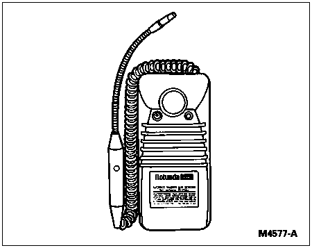
The battery-operated Rotunda R-134a Automatic Calibration Halogen Leak Detector 023-R1003 is an instrument that will locate a smaller refrigerant leak. Follow the directions with the leak detector to obtain absolute accuracy.
When the instrument is set to the ON position, it automatically calibrates itself and is ready for detecting. This R-134a gas detector is equipped with an audio and visual alarm system.
Leak Tracer Dye
Leak tracer dye part number 112-R0040 may be used to locate leaks within the refrigerant system when necessary. All Ford vehicles contain the tracer dye, added in production. The tracer dye placed within the system during production is usable for one season only. Beyond one season it will be necessary to add additional leak tracer dye to the system using Rotunda Dye Injector 164-R2610 or equivalent when leak checking the A/C system. The use of Rotunda 120 Watt UV Lamp 164-R0721 or equivalent will be necessary to locate traces of the tracer dye at the leak.
CAUTION: When servicing or diagnosing an A/C system, approved safety glasses or goggles should always be worn.
NOTE: There is no need to clean any surfaces of the A/C system before using the tracer dye. All petroleum products have a natural blue fluorescence under ultraviolet light, in contrast to the tracer dye's yellow/green color.
Inject 7.39 ml (1/4 ounce) of the tracer dye part number 112-R0040 using Rotunda Dye Injector 164-R2610 or equivalent. Follow instructions included with dye injector for use of the injector tool.
Operate the A/C system to thoroughly mix the tracer dye with the system's compressor oil.
NOTE: Tracer dye combines and circulates with both the compressor oil and the refrigerant. For tracer dye to show leakage in an A/C system, the compressor oil must flow throughout the system. As the refrigerant escapes, it will leave a trace of the compressor oil with the dye at the point of leakage.
Continue to operate the A/C system in order to allow the tracer dye to circulate through the system and penetrate the system's leak(s). The time needed for tracer dye to appear will depend on the size of the leak(s).
When adequate circulation of the dye has been achieved, turn the vehicle off. Check for leaks using Rotunda UV Lamp 164-R0721 or equivalent. Best leak detection results will be achieved in conditions of low ambient light. Leaks will appear as a yellow/green glow when exposed to the UV lamp.
In areas that cannot be reached by the UV lamp, a mechanic's mirror or a nonfluorescent shop towel may be used. If the shop towel method is used, wipe the suspected leak area with the shop towel and inspect the shop towel with the UV lamp. Dye will appear as a yellow/green glow on the shop towel. After the leak is repaired, the traces of dye can be removed using any general purpose oil solvent. If no leak is found, return the vehicle to the customer with instructions to bring it back at a later date to allow time for the fluorescent material to collect at the leak site.
Repair any leaks indicated.
Repeat Steps 2, 3, 4 and 5 to verify that the leak has been repaired. There is no need to add additional dye unless the dye was removed during servicing. Tracer dye part number 112-R0040 can remain in the system indefinitely without harm to the system. However, the fluorescent life span is approximately 500 hours of A/C system use, after which time another infusion of the dye would be required for leak detection purposes.
Install the label included with the tracer dye to the vehicle in an area in the engine compartment where it will be easily seen by a future technician and date the label. Labeling the vehicle will tell others that dye has already been installed.