Install a short piece of heater water hose (approximately 100mm [4 inches] long) onto each tube of the heater core.

Section 12-00: Climate Control System, Service | 1996 F-150, F-250, F-350, F-Super Duty and Bronco, F-Super Duty Motorhome Chassis Workshop Manual |
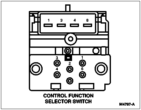
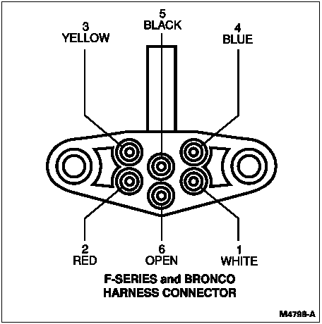
| Function Selector Switch Vacuum Application | ||||||||
|---|---|---|---|---|---|---|---|---|
| Vacuum Port and Hose Color | Function (Vacuum Motor) | Detent Position | ||||||
| Max A/C | Norm A/C | Vent | Off | Floor | Mix | Def | ||
| 1—Yellow | Floor-Panel | V | V | V | V | V | V | A |
| 2—Black | Source | V | V | V | V | V | V | V |
| 3—Blue | Panel-Defrost | V | V | V | A | A | A | A |
| 4—White | Outside-Recirc. | V | A | A | V | A | A | A |
| 5 | Not Used | — | — | — | — | — | — | — |
| 6—Red | Full-Floor | V | V | V | V | V | A | A |
| Function Selector Switch Vacuum Application | ||||||
|---|---|---|---|---|---|---|
| Vacuum Port and Hose Color | Function (Vacuum Motor) | Detent Position | ||||
| Vent | Floor | Off | Mix | Def | ||
| 1 — Yellow | Floor-Panel | V | V | V | V | A |
| 2 — Black | Source | V | V | V | V | V |
| 3 — Blue | Panel-Defrost | V | A | A | A | A |
| 4 — White | Outside-Recirc. | A | A | V | A | A |
| 5 | Not Used | — | — | — | — | — |
| 6 — Red | Full-Floor | V | V | V | A | A |
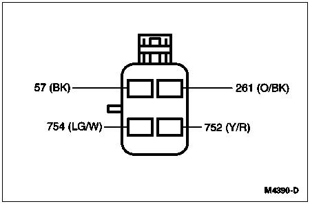
| To Test | Continuity |
|---|---|
| Medium-Low Speed | 261 (O/BK) and 752 (Y/R) |
| Medium Speed | 261 (O/BK) and 754 (LG/W9) and 752 (Y/R) |
| High Speed | 261 (O/BK) and 57 (BK) and 754 (LG/W) |
Heater Core
Plugged Heater Core
Check to ensure the engine coolant is at the proper level, then start the engine and let it run until it is warmed to operating temperature. Turn on the heater and feel the inlet and outlet heater water hoses (18472) to the heater core (18476). If the inlet heater water hose is hot and outlet heater water hose is cooler, the heater core may be plugged.
NOTE: Make sure that an appropriate container is used to collect any coolant that is lost during the heater core bleed procedure.
To bleed air from heater core, remove the hose at the outlet connection of the heater core (hose leading to the water pump). Allow any trapped air to flow out. When a continuous flow of coolant is obtained, connect the hose to the core. Do not overtighten heater hose clamps.
Pressure Test
Drain the cooling system.
Disconnect the heater water hoses from the heater core. If constant tension clamps are used, be sure they are properly positioned.
Install a short piece of heater water hose (approximately 100mm [4 inches] long) onto each tube of the heater core.

Fill the heater core and heater water hoses with water and install Plug BT-7422-B and Adapter BT-7422-A from Radiator/Heater Core Pressure Tester 014-R1052 or equivalent in the ends of the heater water hoses. Secure the heater water hoses to the heater core, plug and adapter with clamps.
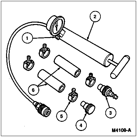
| Item | Part Number | Description |
|---|---|---|
| 1 | — | Bleed Valve (Part of 014-R1052) |
| 2 | 014-R1052 | Radiator/Heater Core Pressure Tester |
| 3 | 7422 | Adapter B |
| 4 | 7422 | Plug |
| 5 | 8287 | Hose Clamp |
| 6 | 18C266 | Heater Hose (4 Inches Long) |
Attach Radiator/Heater Core Pressure Tester 014-R1052 or equivalent to the adapter. Close the bleed valve at the base of the gauge and pump 207 kPa (30 psi) of air pressure into the heater core.
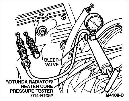
Observe the pressure gauge for a minimum of three minutes. The pressure should not drop.
If the pressure does not drop, no leaks are indicated.
If the pressure drops, check the connections at the core for leaks. If the heater water hoses do not leak, remove the heater core from the vehicle and test the heater core as described in this section. Refer to Section 12-02 for removal and installation procedures for the heater core.
Blower Motor
To test the blower motor (18527), connect a No. 10 (or larger diameter) jumper wire directly from the positive battery terminal to the positive lead of the blower motor. If the blower motor runs, the concern must be external to the blower motor. If the blower motor will not run, connect a No. 10 (or larger diameter) jumper wire from the ground lead of the blower motor to a good ground. If the blower motor runs, the fault is in the ground circuit. If after testing the positive and negative sides of the blower motor, the blower motor still will not run, the blower motor must be replaced.
Blower Motor Resistor
To test the blower heater blower motor switch resistor (18591) as well as the internal thermal limiter, check continuity for shorts or opens with a self-powered test lamp. If the unit indicates an open or short, it cannot be repaired and will require replacement.
A/C Relay, 4.9 California Only
Testing of the A/C relay can be accomplished through the use of three No. 10 (or larger diameter) jumper wires and Rotunda 73 Digital Multimeter 105-R0051 or equivalent. Locate the A/C relay in the power distribution box in the engine compartment and remove (unplug) the relay. Using two jumper wires, connect the relay at Pins 86 and 30 directly to the positive battery terminal. Using Rotunda 73 Digital Multimeter 105-R0051 or equivalent, set in the Volts position, check for voltage at Pin 87a. If battery voltage is not indicated, replace the relay. If battery (10655) voltage is indicated, connect a third jumper wire to Pin 85 of the A/C relay and ground the jumper wire to a known good ground. Check for voltage at Pin 87. If battery voltage is not indicated, replace the A/C relay.