Section 11-05: Steering Column Switches
1996 F-150, F-250, F-350, F-Super Duty, F-Super Duty Motorhome and Bronco Workshop Manual
REMOVAL AND INSTALLATION

Multi-Function Switch

Removal

  1. Disconnect battery ground cable (14301).

  1. Remove the steering column shroud (3530).

  1. Remove two self-tapping screws that attach the multi-function switch (13K359) to the steering column tube casting. Disengage multi-function switch from casting.

  1. Disconnect the two electrical connectors, using caution not to damage the locking tabs. Do not damage PRNDL cable.


    Multi-Function Switch, F-Series and Bronco
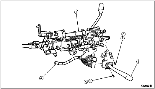


    ItemPart NumberDescription
    13514Steering Column Tube
    2390345-S36Screw
    313K359Multi-Function Switch
    4Wiring to Multi-Function Switch (Part of Main Wiring Harness 14401)
    ATighten to 2-3 Nm
    (18-27 Lb-In)


    Multi-Function Switch, F-Super Duty Motorhome
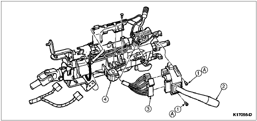


    ItemPart NumberDescription
    1390345-S36Screw
    213K359Multi-Function Switch
    314A320Headlamp Dimmer Switch Jumper Wiring
    43F723Steering Actuator Housing
    ATighten to 2-3 Nm
    (18-27 Lb-In)

Installation

  1. Install the two switch electrical connectors to full engagement. The wiring for the switch is to be routed under the PRNDL cable.

  1. Align the mounting holes on multi-function switch with the holes in the steering column tube casting. Install two self-tapping screws making sure to start the screws in the previously tapped holes. Tighten to 2-3 Nm (18-27 lb-in).

  1. For automatic transmission (7003), verify that the PRNDL adjustment is correct.

  1. Install the steering column shroud.

  1. NOTE: When the battery has been disconnected and reconnected, some abnormal drive symptoms may occur while the powertrain control module (PCM) (12A650) relearns its adaptive strategy. The vehicle may need to be driven 16 km (10 miles) or more to relearn the strategy.

    Connect the battery ground cable.

  1. Check the steering column tube (3514) for proper operation.