Section 11-04: Steering Column | 1996 F-150, F-250, F-350, Bronco, F-Super Duty Chassis Cab and Motorhome Chassis Vehicles Workshop Manual |
![]() WARNING: THE ELECTRICAL CIRCUIT FOR AIR BAG DEPLOYMENT IS POWERED DIRECTLY FROM THE BATTERY AND BACKUP POWER SUPPLY. TO AVOID ACCIDENTAL DEPLOYMENT AND POSSIBLE PERSONAL INJURY, THE BATTERY POSITIVE CABLE MUST BE DISCONNECTED FOR A MINIMUM OF ONE MINUTE BEFORE BEGINNING WORK TO DE-ENERGIZE THE BACKUP POWER SUPPLY.
WARNING: THE ELECTRICAL CIRCUIT FOR AIR BAG DEPLOYMENT IS POWERED DIRECTLY FROM THE BATTERY AND BACKUP POWER SUPPLY. TO AVOID ACCIDENTAL DEPLOYMENT AND POSSIBLE PERSONAL INJURY, THE BATTERY POSITIVE CABLE MUST BE DISCONNECTED FOR A MINIMUM OF ONE MINUTE BEFORE BEGINNING WORK TO DE-ENERGIZE THE BACKUP POWER SUPPLY.
Removal
![]() CAUTION: Make sure air bag sliding contact internal lock is engaged. Hub should not turn more than 45 degrees in either direction.
CAUTION: Make sure air bag sliding contact internal lock is engaged. Hub should not turn more than 45 degrees in either direction.
Make sure front wheels (1007) are in the straight-ahead position and steering column shaft alignment mark is at the 12 o'clock position.
Disconnect battery to starter relay cable (14300) for at least one minute to let the air bag backup power supply discharge.
Remove steering wheel (3600) as described in this section.
Remove steering column upper and lower steering column shrouds (3530) as described in this section.
Disconnect three air bag sliding contact electrical connectors from main wiring (14401) at steering column bend bracket.
Using door trim removal tool, remove air bag sliding contact electrical connectors from bend bracket.
![]() CAUTION: Do not remove wire harness clips from wire bundle.
CAUTION: Do not remove wire harness clips from wire bundle.
Using door trim removal tool, disconnect two wire harness clips from column.
Remove key warning buzzer contact and anti-theft contact from ignition lock cylinder pocket of steering column lock cylinder housing (3511).
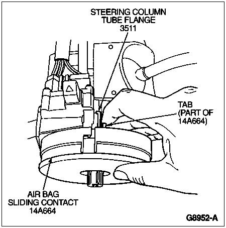
Remove air bag sliding contact (14A664) by pushing snap back at 6 o'clock position first, then 3 o'clock position, then 12 o'clock position and remove from steering shaft.

Installation
Make sure front wheels are in the straight-ahead position and steering column shaft alignment mark is at the 12 o'clock position.
Align air bag sliding contact to column shaft and mounting tabs and slide onto shaft. Push on air bag sliding contact to snap three tabs onto steering column tube flange.
Install air bag sliding contact cable clips into holes in steering column.
Install air bag sliding contact connector retainers into provided holes in steering column bend bracket.
Plug main wiring harness connectors into three air bag sliding contact connectors.
Install key warning buzzer contact and anti-theft contact into ignition lock cylinder pocket in steering column tube flange. Make sure contacts do not slip out of ignition lock cylinder pocket.
Install upper and lower steering column shrouds as described in this section.
Install steering wheel.
NOTE: When the battery has been disconnected and reconnected, some abnormal drive symptoms may occur while the powertrain control module (PCM) (12A650) relearns its adaptive strategy. The vehicle may need to be driven 16 km (10 miles) or more to relearn the strategy.
Connect battery to starter relay cable. Refer to Section 01-20B.
Verify air bag warning indicator operation.