Section 11-02B: Steering Gear, Power, Ford
1996 F-150, F-250, F-350, F-Super Duty and Bronco Workshop Manual
DISASSEMBLY AND ASSEMBLY

Steering Gear

NOTE: Do not use solvent on seals. Using a clean workbench and tools, thoroughly clean the exterior of the gear with solvent. Drain off excess hydraulic fluid, if necessary.

NOTE: Handle all parts carefully to avoid nicks, burrs, scratches and dirt.


SPECIAL SERVICE TOOL(S) REQUIRED
DescriptionTool Number
Bench Mounted Holding FixtureT57L-500-B
Adjuster and Lock Nut WrenchT66P-3553-B
Valve Housing to Piston SpacerT66P-3553-C

Disassembly

  1. Hold the steering gear (3504) upside down over a drain pan and cycle the power steering gear input shaft and control (3D517) several times to drain the fluid from the steering gear.

  1. NOTE: The indexing flat on the power steering gear input shaft and control should be facing downward.

    Secure the steering gear in a soft-jawed vise.


    ItemPart NumberDescription
    1Outlet Port (Part of 3504)
    2Inlet Port (Part of 3504)
    3Identification Tag
    (Part of 3504)
    4Sector Shaft Adjusting Screw (Part of 3540)
    53580Steering Gear Sector Shaft Housing Cover
    6Lock Nut (Part of 3540)
    73575Steering Gear Sector Shaft
    8Control Valve Housing
    (Part of 3568)
    93D517Power Steering Gear Input Shaft and Control
  1. Turn the power steering gear input shaft and control to either stop, then turn it back two turns to center the steering gear.

  1. Remove bolts to the steering gear sector shaft housing cover (3580).

  1. Tap the lower end of the steering gear sector shaft (3575) with a soft hammer to loosen it, and lift the steering gear housing end cover (3568) and steering gear sector shaft from the housing as an assembly. Discard the power steering gear control valve housing o-ring (3756).

  1. NOTE: This step is required only when it is necessary to remove the steering gear sector shaft from the sector assembly.

    Remove the nut from the sector shaft adjusting screw. Turn the steering gear sector shaft housing cover counterclockwise and remove it from the sector shaft adjuster screw.

  1. Remove the valve housing attaching bolts and identification tag. Lift the valve housing off the steering gear housing (3548). Remove the valve housing, piston assembly and steering gear sector shaft housing cover gasket (3581). Discard the gasket.

  1. NOTE: If valve housing or the power steering gear input shaft seals (3D526) are to be replaced, proceed to Step 11. If steering gear sector shaft housing oil seal (3591) is to be replaced go to Steering Gear Housing in the Disassembly and Assembly portion of this section. Steering gear worm ball (3647) needs to be removed if power steering gear input shaft seal is to be replaced.

    With the piston held so the steering gear ball return guide (3523) faces up, remove the ball guide clamp screws and steering gear ball return guide clamp (3544).

  1. With a finger over the opening in the steering gear ball return guide, turn the piston so the steering gear ball return guide faces down over a clean container. Let the steering gear ball return guide drop into the container.


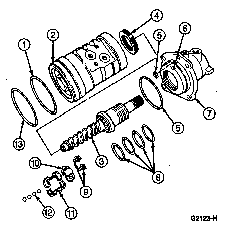
    ItemPart NumberDescription
    1Piston Ring (Part of 3E502)
    2Piston (Part of 3D517)
    33D517Power Steering Gear Input Shaft and Control
    43D627Power Steering Gear Race Nut
    5O-Ring (Part of 3D517)
    6382095-SRace Lock Nut Setscrew
    7Valve Housing
    (Part of 3504)
    8Valve Sleeve Seals
    (Part of 3D517)
    9388889-SScrews
    103544Steering Gear Ball Return Guide Clamp
    113523Steering Gear Ball Return Guide
    123647Steering Gear Worm Ball
    133805Power Steering Gear Piston Seal
  1. Rotate the power steering gear input shaft and control from stop to stop until all balls fall from the piston into the container. The power steering gear input shaft and control can then be removed from the piston. Inspect the piston bore to make sure all steering gear worm balls have been removed.

  1. Install the power steering gear input shaft and control in the Bench Mounted Holding Fixture T57L-500-B and loosen the Allen head race lock nut screw from the valve housing.

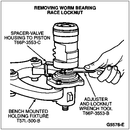
  1. Remove the power steering gear race nut (3D627) using Adjuster and Lock Nut Wrench T66P-3553-B and Valve Housing to Piston Spacer T66P-3553-C.

  1. Carefully slide the power steering gear input shaft and control and steering gear input worm gear and rack (3524) out of the valve housing.


Assembly

  1. Mount the power steering gear input shaft and control in the Bench Mounted Holding Fixture T57L-500-B with the flanged end up.

  1. Apply a light coat of Premium Power Steering Fluid E6AZ-19582-AA or equivalent meeting Ford specification ESW-M2C33-F to the Teflon® rings on the valve sleeve.

  1. Carefully install the power steering gear input shaft and control valve in the steering gear housing.

  1. Install the power steering gear race nut in the housing and tighten to 75-122 Nm (55-90 lb-ft).

  1. Install the Allen head race lock nut setscrew through the valve housing and tighten to 1.7-2.8 Nm (15-25 lb-in).

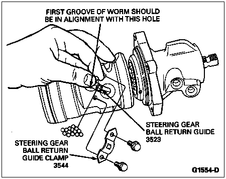
  1. Place the piston on the bench with the ball guide holes facing up. Insert the power steering gear input shaft and control into the piston so the first groove is in line with the hole nearest the center of the piston.

  1. Place the steering gear ball return guide in the piston. Turning the power steering gear input shaft and control counterclockwise, place the same steering gear worm balls as were removed in the steering gear ball return guide. During assembly, 27 to 29 balls are required. If all the balls have not been inserted upon reaching the left stop, rotate the power steering gear input shaft and control in one direction then the other while inserting the remaining balls.


  1. Secure the guides in the ball nut with the clamp. Tighten screws to 5-7 Nm (42-70 lb-in).

  1. Apply petroleum jelly or equivalent to the Teflon® seal on the piston.

  1. Place a new steering gear sector shaft housing cover gasket on the valve housing.

  1. Slide the piston and valve into the steering gear housing being careful not to damage the piston ring.

  1. Align the oil passage in the steering gear ball return guide with the passage in the steering gear housing. Place a new O-ring onto the oil passage hole of the steering gear housing. Install identification tag onto the housing. Install, but do not tighten, the attaching bolts. Identification tag is to be installed under upper right valve housing bolt.

  1. Rotate the piston so the teeth are in the same plane as the steering gear sector shaft. Tighten the valve housing attaching bolts to 40-60 Nm (30-44 lb-ft).

  1. Position the steering gear sector shaft housing oil seal in the steering gear housing. Turn the input shaft to center the piston.

  1. Apply petroleum jelly or equivalent to the sector shaft journal, and position the sector shaft and cover assembly in the gear housing. Install the steering gear housing end cover attaching bolts. Tighten the bolts to 75-94 Nm (55-69 lb-ft).

  1. Attach a pound-inch torque wrench to the power steering gear input shaft. Adjust meshload to specification. Refer to Specifications at the end of this section.