Section 10-02: Accelerator Pedal and Linkage
1996 F-150, F-250, F-350, F-Super Duty and Bronco Workshop Manual
REMOVAL AND INSTALLATION

Accelerator Pedal and Sensor Assembly, Diesel Engine


Removal

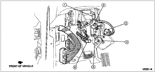
  1. Disconnect the electrical connectors from the idle validation switch and the accelerator pedal position sensor.

  1. Remove the screws holding the accelerator pedal and sensor assembly to the instrument panel (04320).

  1. Remove the accelerator pedal and sensor assembly from the instrument panel.

    Accelerator Pedal Installation, Diesel
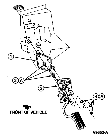
    ItemPart NumberDescription
    19N809Accelerator Control Plate
    2N808382-S426Stud
    39F836Accelerator Pedal and Sensor Assembly
    4N620481-S2Accelerator Pedal and Sensor Assembly Nuts
    ATighten to 21-29 Nm
    (16-21 Lb-Ft)
 

Installation

  1. Position accelerator pedal and sensor assembly to instrument panel and install accelerator pedal and sensor assembly lower nut hand-tight.

  1. Install and tighten the accelerator pedal and sensor assembly nuts to 21-29 Nm (16-21 lb-ft).

  1. Connect the electrical connectors to the idle validation switch and the accelerator pedal position sensor.

Accelerator Pedal Sensors

ItemPart NumberDescription
114401Main Wiring
2Accelerator Pedal Position Sensor (Part of 9F836)
3Pedal Position Sensor Electrical Connector
(Part of 14401)
49F836Accelerator Pedal and Sensor Assembly
5Idle Validation Switch
(Part of 9F836)
6Idle Validation Switch Electrical Connector
(Part of 14401)