Thread Impact Slide Hammer T50T-100-A into Extension Housing Seal Replacer T61L-7657-A through the back of the case. Install the rear case bushing.

Section 07-01C: Transmission, Automatic, 4R70W | 1996 F-150 (4x2) (4x4) and Bronco Vehicles Equipped with 5.0L Engines Workshop Manual |
| Description | Tool Number |
|---|---|
| Extension Housing Seal Replacer | T61L-7657-A |
| Impact Slide Hammer | T50T-100-A |
| Servo Piston Remover/Replacer | T92P-70023-A |
| Gauge Bar | T80L-77003-A |
| Shift Lever Seal Replacer | T74P-77498-A |
| Servo Piston Selection Tool | T80L-77030-A |
| Transmission Range (TR) Sensor (MLPS) Alignment Tool | T93P-70010-A |
If rear case bushing was removed, position replacement rear case bushing on Extension Housing Seal Replacer T61L-7657-A and install in bushing bore through the front of the case (7005).
Thread Impact Slide Hammer T50T-100-A into Extension Housing Seal Replacer T61L-7657-A through the back of the case. Install the rear case bushing.

With transmission in the vertical position, coat No. 9 case rear bearing (7F242) with petroleum jelly and install the No. 9 case rear bearing on the transmission case boss.

Install output shaft (7060), output shaft ring gear and direct clutch as an assembly.

Install retaining ring that supports reverse band.

Install the reverse band. Ensure reverse band is seated on anchor pins.

NOTE: Planetary assembly and planetary gear support cannot be installed unless the notch cut in the planetary gear support is aligned with the overdrive band anchor pin (7F295). Top of planetary gear support should be below snap ring groove.
Install planetary assembly and planetary gear support as a unit.
Align notch in planetary gear support with overdrive band anchor pin.
Rotate the output shaft, if necessary, to align the planetary assembly splines with the direct clutch hub splines.

Install the case to planet support spring (7F277) using a screwdriver to position.

Install center support retaining ring. Reference retaining ring end tab to anchor pin location.

Install forward clutch sun gear, No. 5 forward clutch sun gear bearing, reverse clutch sun gear and No. 4 forward clutch hub bearing.

Install intermediate stub shaft.

Install forward clutch hub and No. 3 forward clutch hub front bearing (7F231).

Install forward clutch assembly.

NOTE: Wiggle the input shaft while engaging the reverse clutch splines. Make sure the reverse clutch cylinder lugs are completely seated in the notches of the reverse sun gear.
Install reverse clutch cylinder assembly and No. 2 forward clutch bearing.

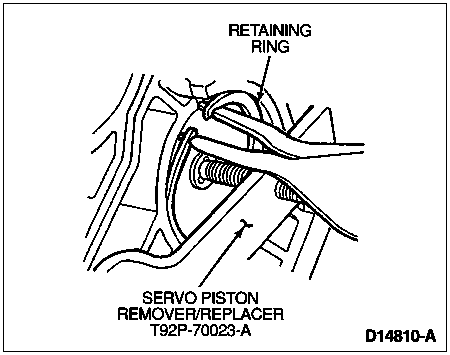
Install overdrive band (7F196) over reverse clutch assembly and position the pocket of the overdrive band against overdrive band anchor pin. Install overdrive servo piston return spring (7F201) and overdrive servo piston assembly. Verify tip of piston assembly engages the pocket of overdrive band. Using Servo Piston Remover/Replacer Tool T92P-70023-A, install piston assembly into the case and compress overdrive servo piston return spring.


Make sure overdrive band anchor pin and tip of the overdrive servo piston assembly are properly positioned against band pockets. Tighten tool forcing screw until piston is below retaining ring groove and install retaining ring, remove tool.

Install intermediate clutch as follows:

With proper intermediate plates selected and installed, perform end clearance check for No. 1 front pump support thrust washer using the same tools.

NOTE: Maintain downward pressure on clutch pack while measuring depth.
Measure the intermediate clutch clearance using Depth Micrometer D80P-4201-A or equivalent and Gauge Bar T80L-77003-A.
Set the gauge bar across the pump case mounting surfaces. The depth at the intermediate clutch separator plate is 42.59-41.73mm (1.677-1.643 inches).
Check the clearance again 180 degrees opposite to ensure the average depth is within tolerance.
If the depth is not within tolerance, the following size selective steel plates are available:
| 1.80-1.7mm (0.071-0.067 Inch) |
| 2.05-1.95mm (0.081-0.077 Inch) |
| 2.31-2.20mm (0.091-0.087 Inch) |
| 2.56-2.46mm (0.101-0.097 Inch) |
Install correct plate and check clearance.
Position the Depth Micrometer D80P-4201-A or equivalent on Gauge Bar T80L-77003-A so that the depth is measured at the reverse clutch drum thrust face. Check the end play 180 degrees opposite to determine the average depth.

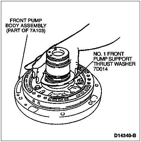
Install No. 1 front pump support thrust washer on pump body using petroleum jelly to hold in place.

Install pump gasket. Make sure pump gasket is positioned and case passages are covered.
To maintain pump-to-case alignment, use a fabricated M8-1.25mm bolt (head removed) as a guide. Install in the 12 o'clock position using petroleum jelly on pump-to-case seal surfaces to aid pump installation.

To aid assembly, grasp input shaft and wiggle shaft while pressing down on pump.

Remove alignment bolt and install pump-to-case bolts. Alternate bolt tightening to "draw" the pump fully into the case. Tighten to 20-26 Nm (15-19 lb-ft).

Place transmission in the horizontal position. Install parking pawl (7A441) and parking pawl return spring (7D070). Slide parking pawl shaft (7D071) into case through parking pawl.

Install output shaft speed sensor (OSS). Tighten bolt to 7-10 Nm (5-7 lb-ft).

Install manual control lever seal using Shift Lever Seal Replacer T74P-77498-A.

Install EPC solenoid.

Install new extension housing gasket (7086) and extension housing (7A039). Tighten bolts to 24-30 Nm (18-22 lb-ft).
Install extension housing seal.

Position manual valve detent lever (7A115) and parking lever actuating rod (7A232) into case. Parking lever actuating rod must be positioned over parking pawl.

Slide manual control lever shaft into case and position through detent. Install nut and tighten to 27-37 Nm (20-27 lb-ft) while holding manual control lever shaft with a crescent wrench.
Install manual lever shaft retaining pin (7B210).
Install fluid screen into case (head first).

NOTE: This is not an ordinary installation procedure and does not compensate for band wear.
Install reverse band servo spring (7D031), reverse band servo piston and rod (7D189). When piston and rod assembly replacement becomes necessary, determine the correct length of the reverse servo piston and rod, proceed as follows.


Install reverse band servo cover (7D036).
Install Servo Piston Remover/Replacer T92P-70023-A to transmission case.
Tighten screw on Servo Piston Remover/Replacer T92P-70023-A to allow enough clearance to install retaining ring.
![]() CAUTION: Make sure reverse servo retaining ring is completely seated before removing tool.
CAUTION: Make sure reverse servo retaining ring is completely seated before removing tool.
Install reverse servo retaining ring and remove tool.

NOTE: Retainer is secured by main control.
Install the following components for 2-3 shift accumulator:

| Item | Part Number | Description |
|---|---|---|
| 1 | 7F290 | 2-3 Accumulator Piston Upper Seal |
| 2 | 7F251 | 2-3 Shift Accumulator Piston |
| 3 | 7F249 | 2-3 Accumulator Piston Lower Seal |
| 4 | 7F285 | 2-3 Shift Accumulator Piston Spring |
| 5 | 7B264 | 2-3 Shift Accumulator Spring Retainer |
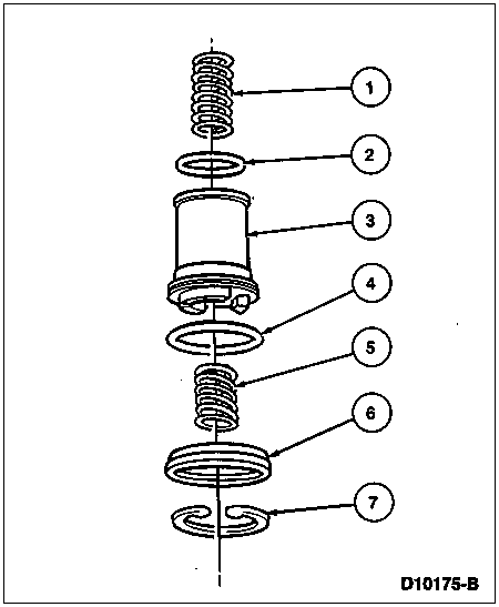
Install the following components for 1-2 shift accumulator:

| Item | Part Number | Description |
|---|---|---|
| 1 | 7F284 | 1-2 Shift Spring |
| 2 | 7F248 | 1-2 Shift Accumulator Piston Seal |
| 3 | 7F251 | 1-2 Shift Accumulator Piston |
| 4 | 7F249 | 1-2 Shift Accumulator Piston Lower Seal |
| 5 | 7F284 | 1-2 Shift Spring |
| 6 | 7G300 | 1-2 Accumulator Cover and Seal Assembly |
| 7 | 7384 | Internal Retaining Ring |

NOTE: Tab on connector is secured by main control.
Align and install wiring connector into case. Inspect O-ring and replace if required.

Install main control valve body (7A100) using the two alignment bolts as a guide.
Install the EPC solenoid bracket. Loosely install one long 6mm bolt.

Loosely install 11 long and 12 short valve body-to-case retaining bolts.
Install manual valve detent spring and one bolt.

Tighten the 25 main control valve body-to-case retaining bolts to 9-11 Nm (80-100 lb-in) in sequence as shown in the following illustration.

Connect wiring connectors to transmission fluid temperature sensor, shift solenoids (7G484), EPC solenoid and TCC solenoid.

Install filter and seal assembly.

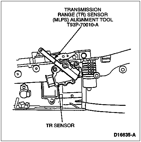
Install TR sensor on manual control lever shaft and loosely install bolts.

NOTE: PARK is the last detent when the manual control lever is full forward. Return two detents toward output shaft for NEUTRAL.
Position manual control lever in NEUTRAL. Insert Transmission Range (TR) Sensor (MLPS) Alignment Tool T93P-70010-A into slots. Align all three slots on TR sensor with three tabs on tool.

Tighten TR sensor bolts to 9-11 Nm (80-100 lb-in).
Install manual control lever.
Install manual control lever shaft nut using a socket while holding the manual control lever with a crescent wrench. Tighten nut to 27-39 Nm (20-29 lb-ft).
Install pan magnet in transmission pan.
Install new pan to case gasket and transmission pan. Tighten all bolts to 12-15 Nm (9-11 lb-ft).
