
Section 07-01C: Transmission, Automatic, 4R70W | 1996 F-150 (4x2) (4x4) and Bronco Vehicles Equipped with 5.0L Engines Workshop Manual |
Transmission, Automatic, 4R70W

| Item | Part Number | Description |
|---|---|---|
| 1 | 7902 | Torque Converter |
| 2 | 7B164A | Intermediate Clutch |
| 3 | 7B164E | Reverse Clutch |
| 4 | 7B164D | Forward Clutch |
| 5 | 7B164B | Direct Clutch |
| 6 | 7F207 | Forward Clutch Cylinder and Shaft |
| 7 | 7F351 | Intermediate Stub Shaft |
| 8 | 7060 | Output Shaft |
| 9 | 7A089 | Planetary One-Way Clutch |
| 10 | 7D095 | Reverse Clutch Band |
| 11 | 7F196 | Overdrive Band |
| 12 | 7A089 | Intermediate One-Way Clutch |
Torque Converter
The torque converter (7902) is a four-element converter. It contains the standard three elements which transmit and multiply torque:
The torque converter clutch increases fuel economy in 3rd and 4th gears.
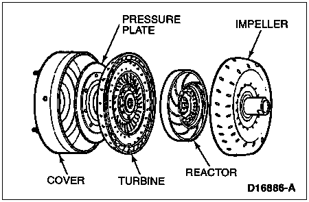
The operation of the torque converter components is as follows:
The addition of a torque converter clutch to the torque converter provides a mechanical link between the converter housing and the engine, allowing for direct transfer of power from the engine to the geartrain.
The torque converter clutch is applied and released by fluid pressure, which is controlled by the powertrain control module (PCM) (12A650) through a torque converter clutch solenoid (TCC solenoid) (7G136) in the main control valve body (7A100).
Impeller and Cover
The primary functions of the impeller and cover assembly are to drive the impeller blades, contain hydraulic fluid and provide a mating surface for the converter clutch pressure plate. In addition, the impeller hub drives the fluid pump gear.
Turbine
The turbine is a sectioned, donut-shaped steel stamping that is splined to the input shaft. It is driven by fluid from the impeller and transmits this power to the geartrain. Because of its basic shape, the turbine automatically directs fluid back to the impeller.
Reactor
The reactor redirects the fluid flow returned to the impeller from the turbine so that the fluid moves in the same direction as engine/impeller rotation. This action aids in torque multiplication because it adds torque to that already supplied by the engine. The reactor contains a one-way clutch that holds it stationary when torque multiplication is necessary, but allows freewheeling at higher speeds when torque multiplication is not necessary.
Torque Converter Clutch
The pressure plate attaches to the back of the turbine and can be applied against the cover to allow for a mechanical transfer of engine torque to the geartrain. This occurs mainly in third and fourth gears when torque multiplication is no longer necessary. (Converter clutch application may also occur in second gear under certain conditions.)
The pressure plate works much like a regular mechanical clutch. Apply, release and controlled slip of the clutch are controlled by opposing fluid forces on each side of the pressure plate.
Torque Converter Sectional View

| Item | Part Number | Description |
|---|---|---|
| 1 | — | Torque Converter Cover (Part of 7902) |
| 2 | — | Turbine (Part of 7902) |
| 3 | — | Impeller (Part of 7902) |
| 4 | — | Reactor (Part of 7902) |
| 5 | — | Torque Converter Clutch (Part of 7902) |
Geartrain
Power is transmitted from the torque converter to the Ravigneaux geartrain components through the input shaft and forward clutch cylinder.
| Gear Ratios |
|---|
| 1st gear 2.84 to 1 |
| 2nd gear 1.55 to 1 |
| 3rd gear 1.00 to 1 |
| 4th gear 0.70 to 1 |
| Reverse 2.32 to 1 |
Planetary Gearset
The planetary gearset in the transmission is a Ravigneaux-type set consisting of the following components:
Members are driven or held to produce four forward gear ratios plus one reverse ratio.
Input Shaft
The forward clutch cylinder and shaft (7F207) transfers speed and torque from the converter turbine to the geartrain. This shaft is splined to the turbine on one end and to the forward clutch sun gear and input shaft on the other end.
Stub Shaft
The input shaft transfers power from the turbine to the planetary carrier (through the direct clutch) during third and fourth gear operation.
Output Shaft
The output shaft provides torque to the propeller shaft and rear axle assembly (4200). It is driven by the ring gear (7A153) of the planetary gearset.
Forward Clutch Cylinder and Shaft
The forward clutch cylinder and shaft transfers speed and torque from the converter turbine to the geartrain. This shaft is splined to the turbine on one end and to the forward clutch sun gear and input shaft on the other end.
Apply Components
There are eight apply devices used to drive or hold the planetary gearset members. The following is a description of each apply component.
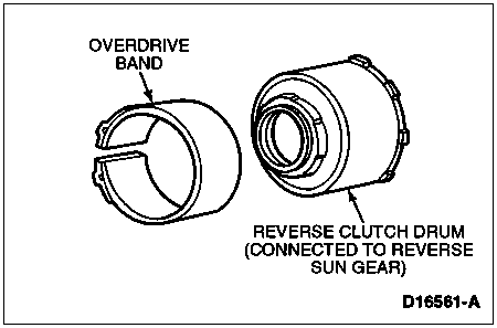
Overdrive Band
The overdrive band (7F196) holds the reverse clutch drum (7D044) stationary in fourth gear and in manual range second gear. This action causes the reverse sun gear to be held in these ranges.
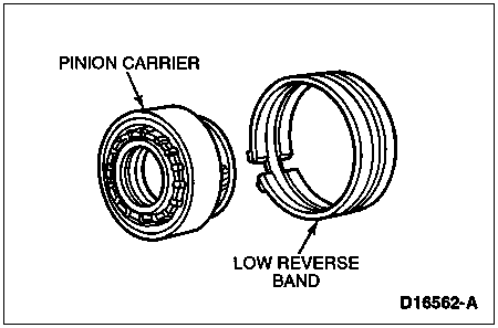
Low and Reverse Band
The low and reverse band holds the pinion carrier stationary in reverse. It is also applied in 1st gear, manual 1 range, to provide engine braking.
Forward Clutch
The forward clutch couples the input shaft to the forward sun gear in 1st, 2nd and 3rd gears.

Direct Clutch
The direct clutch couples the input shaft to the planet carrier (through the stub shaft) in 3rd and 4th gears.

Reverse Clutch
The reverse clutch couples the input shaft to the reverse sun gear. It is applied in reverse range only.

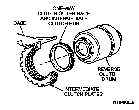
Intermediate Clutch
The intermediate clutch works with the intermediate one-way clutch to hold the reverse sun gear stationary in 2nd gear. The intermediate clutch remains applied in 3rd and 4th gears, but does not transmit power.
Planetary (Low) One-Way Clutch
The planetary (low) one-way clutch is a roller clutch that holds the pinion carrier stationary in first gear, (D) and D ranges. During automatic coasting downshifts into first gear ((D) and D ranges), it freewheels so that there is no engine braking.

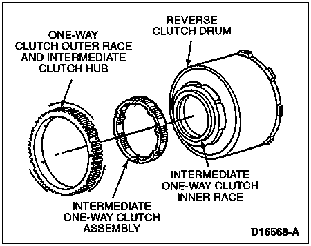
Intermediate One-Way Clutch
The intermediate one-way clutch is a roller clutch that works with the intermediate friction clutch to hold the reverse sun gear stationary in second gear during acceleration. This one-way clutch freewheels in 3rd gear and during coasting in 2nd gear, (D) and D ranges.
Hydraulic System
4R70W Hydraulic Components

| Item | Part Number | Description |
|---|---|---|
| 1 | 7A106 | Front Pump Body Assembly |
| 2 | 7005 | Case Assembly |
| 3 | 7A194 | Transmission Pan |
| 4 | 7A191 | Transmission Pan Gasket |
| 5 | 7A098 | Fluid Filter and Seal Assembly |
| 6 | 7A100 | Main Control Assembly |
| 7 | 7A108 | Front Pump Support Assembly |
| 8 | 7D273 | Fluid Tube Connector Assembly (2 Req'd) |
Pump
The transmission uses a gerotor design front pump support and gear (7A103). The pump is more efficient at lower engine speeds. It is also made of aluminum. The pump provides the volume of fluid needed to charge the torque converter, main control assembly, cooling system and lube system. Pump pressure is regulated by the main regulator valve. The pump also has an internal boost circuit.

Filter
All fluid drawn from the pan by the pump passes through the filter. The filter and its accompanying seal are part of the fluid path from the sump (pan) to the fluid pump.
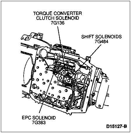
Main Control
The main control valve body houses four electronic solenoids:
Accumulators
1-2 Accumulator — The 1-2 accumulator (in the case) is used to soften the 1-2 shift by absorbing some of the pressure directed to the intermediate clutch. Constant line pressure is applied to the middle section of the 1-2 accumulator piston (7F251), opposing the intermediate clutch pressure until this pressure is enough to overcome line pressure. The top of the piston is exhausted to the sump.
2-3 Accumulator — The 2-3 accumulator is used to soften the 2-3 shift by absorbing some of the direct clutch pressure. Forward clutch pressure is applied to the top side of the accumulator piston, holding the piston down until direct clutch pressure is enough to overcome it. The middle section of the accumulator is exhausted to the sump. The 2-3 accumulator also helps control forward engagement.