Section 07-01A: Transmission, Automatic, E4OD
1996 All F-Series and Bronco with E4OD Automatic Transmission Workshop Manual
INSTALLATION

Transmission — 4x4

Before installing transmission, check wiring harness for damage. Check connectors for electrical integrity (terminal condition, corrosion, contamination and seal integrity). Repair or replace as required.

  1. Place transmission onto Rotunda E4OD Transmission Jack Adapter 014-00763 or equivalent.

  1. On 4x4 models only, install transfer case to transmission. Refer to Section 07-07A, Section 07-07B or Section 07-07C. On F-Super Duty Models, install transmission-mounted parking brake. Refer to Section 06-05 in the Body, Chassis Manual.

  1. Check condition of transmission fluid filler tube O-ring, replace if damaged. Install fluid filler tube.

  1. Rotate torque converter studs to align with flywheel mounting holes.

  1.  CAUTION: Prior to installation of the transmission assembly, the torque converter pilot hub must be properly lubricated.

    Lubricate torque converter pilot hub with Ford Multi-Purpose Grease DOAZ-19584-AA or equivalent, meeting Ford specification ESA-M1C45-A.
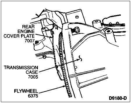
  1. Raise transmission into position while watching for any obstructions. Do not allow torque converter drive flats to disengage from pump gear. Rubber converter drain plug cover may be removed to aid in the alignment of the converter studs. Use care not to damage theflywheel (6375) and converter pilot. The torque converter (7902) must rest squarely against theflywheel. This indicates that the torque converter pilot is not binding in the engine crankshaft (6303).


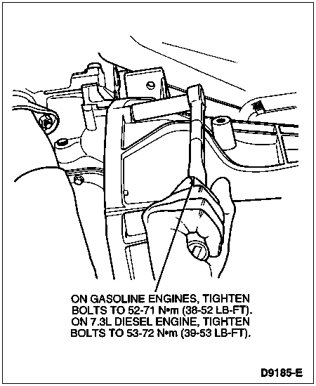
  1. Install transmission-to-engine bolts. Alternately snug-up bolts. On gasoline engines, alternately tighten bolts to 52-71 Nm (38-52 lb-ft). On 7.3L diesel engines, alternately tighten bolts to 53-72 Nm (39-53 lb-ft).


  1. Install converter housing access plug (7N171), if removed.

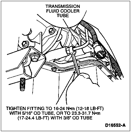
  1. NOTE: Case connector fitting should be held with wrench to prevent it from moving when tightening tube nut.

    Install transmission fluid cooler tubes to transmission fittings. Tighten to 16-24 Nm (12-18 lb-ft) on all applications using 5/16-inch OD fluid cooler tube or to 23.3-31.7 Nm (17-24.4 lb-ft) on all applications using 3/8-inch OD fluid cooler tube.


  1. Install transmission support crossmember (6A023) and transmission retaining bolts. Make sure that wiring harness is properly routed.


Crossmember Installation, F-Series, Bronco, F-Super Duty and Motorhome Vehicles


ItemPart NumberDescription
16096Rear Engine Support Bracket (RH)
26A023Transmission Support Crossmember
360091Insulator and Retainer
4390066Screw and Washer
56096Rear Engine Support Bracket (LH)
6N621945Nut and Washer
7N802114Bolt
8N800937Nut
ATighten to 81-108 Nm
(60-80 Lb-Ft) for F-Series and Bronco. Tighten to 68-95 Nm (50-70 Lb-Ft) for F-Super Duty and Motorhome Applications.
BTighten to 60-95 Nm
(44-70 Lb-Ft)
  1. Remove safety strap and universal high lift transmission jack.

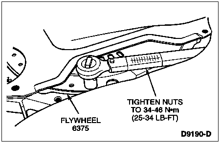
  1. Rotate crankshaft using a 15/16-inch socket on front pulley bolt to gain access to torque converter studs. Install new converter stud nuts using a 9/16-inch socket. Tighten to 34-46 Nm (25-34 lb-ft).


  1. Install starter motor (11001). Refer to Section 03-06A or Section 03-06B.

  1. Install rear engine plate cover and lower dust cover bolts (or screws). Tighten all bolts to 18-23 Nm (13-17 lb-ft). On 7.5L engines tighten dust cover to plate screws 3-7 Nm (30-60 lb-in).


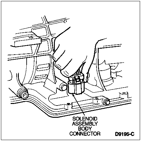
  1. Completely seat solenoid body connector into solenoid body assembly receptacle by pushing on the top of the connector. An audible click indicates full contact. Verify connection by pulling on harness.


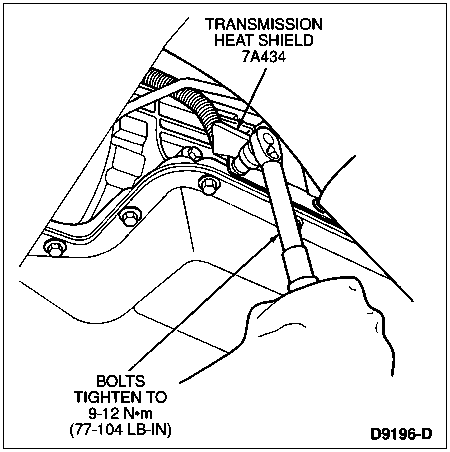
  1. Install transmission heat shield (7A434) with off-set bending inward. Tighten to 9-12 Nm (77-104 lb-in).


  1. On 4x4 models only, install new wire harness locators into transmission support crossmember

  1. Install new wire harness locator into extension housing wire bracket.

  1. Install four-wheel drive switch connector, if equipped.

  1. Connect transfer case shift linkage, if equipped. Refer to Section 07-07B.

  1. Install Transmission Range (TR) sensor connector. An audible click indicates full connection.

  1. Install shift cable, or linkage on F-Super Duty and Motorhome vehicles. Refer to Section 07-05.

  1. Install parking brake (F-Super Duty). Refer to Section 06-05 in the Body, Chassis Manual.

  1.  CAUTION: Be careful not to nick or damage extension housing seal during driveshaft installation.

    Prior to installation, lightly coat slip yoke with High Temperature 4x4 Front Axle and Wheel Bearing Grease E8TZ-19590-A or equivalent meeting Ford specification ESA-M1C198-A.

  1. Install rear driveshaft. Refer to Section 05-01.

  1. On 4x4 models only, install front driveshaft. Refer to Section 05-01.

  1. Remove safety stands and lower vehicle.

  1. NOTE: When the battery has been disconnected and reconnected, some abnormal drive symptoms may occur while the powertrain control module (PCM) (12A650) relearns its adaptive strategy. The vehicle may need to be driven 16 km (10 miles) or more to relearn the strategy.

    Connect battery ground cable (14301).

  1. Fill the transmission to the proper level with Motorcraft MERCON® Multi-Purpose Automatic Transmission Fluid XT-2-QDX or MERCON® equivalent. Refer to Fluid Capacity chart under Specifications.