Section 07-01A: Transmission, Automatic, E4OD | 1996 All F-Series and Bronco with E4OD Automatic Transmission Workshop Manual |
Engine Idle Speed Check
Refer to the Powertrain Control/Emissions Diagnosis Manual OBDI or OBDII for the appropriate procedure.
Line Pressure Test
| Description | Tool Number |
|---|---|
| Pressure Gauge | T57L-77820-A |
![]() CAUTION: Perform line pressure test prior to performing stall speed test. If line pressure is low at stall, do not perform stall speed test or further transmission damage will occur. DO NOT MAINTAIN WIDE-OPEN THROTTLE in any gear range FOR MORE THAN FIVE (5) SECONDS.
CAUTION: Perform line pressure test prior to performing stall speed test. If line pressure is low at stall, do not perform stall speed test or further transmission damage will occur. DO NOT MAINTAIN WIDE-OPEN THROTTLE in any gear range FOR MORE THAN FIVE (5) SECONDS.
This test verifies the line pressure is within specifications.
Connect pressure gauge to line pressure tap.

Start engine and check line pressures. Refer to the following chart to determine if line pressure is within specification.
If line pressure is not within specifications, perform On-Board Diagnostics and Pinpoint Test E, air pressure check and service main control system or pump as required.
| Gear | Line Pressure — Idle | Line Pressure — Stall | ||
|---|---|---|---|---|
| kPa | psi | kPa | psi | |
| P, N | 379-448 | 55-65 | — | — |
| R | 517-683 | 75-99 | 1655-1827 | 240-265 |
| (D), 2 | 379-448 | 55-65 | 1076-1200 | 156-174 |
| 1 | 517-683 | 75-99 | 1082-1282 | 157-186 |
| Low at Idle in All Ranges | High at Idle in All Ranges | ||||
|---|---|---|---|---|---|
| Check low fluid level, restricted inlet filter, loose main body, solenoid body or accumulator body-to-case bolts, excessive leakage in pump, case, control bodies, sticking main regulator valve, damaged filter assembly and seal, damaged gaskets or valve body separating plate. | Check main regulator valve, solenoid body and wiring harness. Run Quick Test referred to in Diagnostics in this section. | ||||
| Low Only in | |||||
| P | R | N | (D) | 2 | 1 |
| Check valve bodies 7A100 | Check separator reinforcing plate, coast clutch, low/reverse clutch or direct clutch, valve bodies 7A100, 7G422 | Check valve bodies 7A100 | Check forward clutch, valve bodies 7A100 | Check forward clutch, coast clutch or intermediate band servo, valve bodies 7A100, 7G422 | Check forward clutch, low/reverse clutch or coast clutch, valve bodies 7A100 |
Stall Speed Test
![]() WARNING: APPLY THE SERVICE AND PARKING BRAKES FIRMLY WHILE PERFORMING EACH STALL TEST.
WARNING: APPLY THE SERVICE AND PARKING BRAKES FIRMLY WHILE PERFORMING EACH STALL TEST.
![]() CAUTION: Perform line pressure test prior to performing stall test. If line pressure is low at stall, do not perform stall test or further transmission damage will occur.
CAUTION: Perform line pressure test prior to performing stall test. If line pressure is low at stall, do not perform stall test or further transmission damage will occur.
NOTE: The stall test should only be performed with the engine and transmission at normal operating temperatures.
The stall test checks the operation of the following items:
Connect tachometer to engine.
After testing each of the following ranges, (D), 2, 1 and R, move gearshift selector lever to N (neutral) and run engine for about 15 seconds to allow torque converter (7902) to cool before testing next range.
![]() CAUTION: If engine rpm recorded by the tachometer exceeds maximum specified rpm, release accelerator pedal immediately. Clutch or band slippage is indicated.
CAUTION: If engine rpm recorded by the tachometer exceeds maximum specified rpm, release accelerator pedal immediately. Clutch or band slippage is indicated.
![]() CAUTION: Do not maintain wide-open throttle (WOT) in any gear range for more than five seconds.
CAUTION: Do not maintain wide-open throttle (WOT) in any gear range for more than five seconds.
Press accelerator pedal to floor (WOT) in each range. Record rpm reached in each range. Stall speeds should be in appropriate range.
| Series | Axle | Engine | Min. | Max. |
|---|---|---|---|---|
| All | 3.08/3.31/3.55 | 4.9L | 1595 | 1912 |
| All | 3.08/3.55/4.10 | 5.0L | 2073 | 2494 |
| Bronco, F-150, F-250 LD | 3.08/3.55/4.10 | 5.8L | 2275 | 2712 |
| HD F-250, F-350 | 3.55/4.10 | 5.8L | 2256 | 2705 |
| All | 3.55/4.10/4.63/5.13 | 7.3L Diesel | 1945 | 2277 |
| F-Series (Only) | 3.55/4.10/4.63/5.13 | 7.5L | 1972 | 2350 |
If the stall speeds were too high, refer to the following Stall Speed Diagnosis Chart. If the stall speeds were too low, first check engine tune-up. If engine is OK, remove torque converter and check torque converter reactor one-way clutch for slippage.
| Range | Possible Source |
|---|---|
| (D) |
|
| R |
|
| 2 |
|
| 1 |
|
Air Pressure Tests
A no-drive condition can exist, even with correct transmission fluid pressure, because of inoperative clutches or bands. Refer to the Band/Clutch Application Chart No. 601, following Air Pressure Tests, Test Procedures, to determine the appropriate elements. A clutch concern may be located through a series of checks by substituting air pressure for fluid pressure to determine the location of the malfunction.
Example: When the gearshift selector lever is in a forward gear range ((D), 2, 1) a no-drive condition may be caused by an inoperative forward clutch.
Test Procedures
Drain the transmission fluid. Remove transmission pan.
Remove filter assembly and seal solenoid body and the control assemblies.
The inoperative clutches may be located by applying air pressure into the appropriate clutch port. See the following Air Pressure Test Port Locations diagram for clutch port locations.
Apply air pressure to the appropriate clutch port (see diagram). A dull thud may be heard, or movement felt when a clutch piston is applied. If clutch seals or check ball are leaking a hissing may be heard.
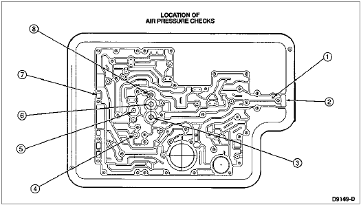
| Item | Part Number | Description |
|---|---|---|
| 1 | — | Reverse Clutch Feed |
| 2 | — | Rear Lube |
| 3 | — | Intermediate Lube |
| 4 | — | Intermediate Clutch Feed |
| 5 | — | Overdrive Clutch Feed |
| 6 | — | Forward Clutch Feed |
| 7 | — | Coast Clutch Feed |
| 8 | — | Direct Clutch Feed |
| Gear | Friction Elements | ||||||
|---|---|---|---|---|---|---|---|
| Intermediate Band | Coast | Overdrive | Intermediate | Direct | Forward | Reverse | |
| (D) first | — | ab | — | — | — | apply | — |
| (D) second | — | ab | — | apply | — | apply | — |
| (D) third | — | ab | — | apply | apply | apply | — |
| (D) fourth | — | — | apply | apply | apply | apply | — |
| 1 | — | apply | — | — | — | apply | apply |
| 2 | apply | apply | — | apply | — | apply | — |
| reverse | — | apply | — | — | apply | — | apply |
| Gear | One-Way Clutches | |||||
|---|---|---|---|---|---|---|
| Overdrive | Intermediate | Low | ||||
| Drive | Coast | Drive | Coast | Drive | Coast | |
| (D) first | HOLD | ab | — | — | HOLD | O/R |
| (D) second | HOLD | ab | HOLD | O/R | O/R | O/R |
| (D) third | HOLD | ab | O/R | O/R | O/R | O/R |
| (D) fourth | O/R | O/R | O/R | O/R | O/R | O/R |
| 1 | HOLD | CC | — | — | HOLD | — |
| 2 | HOLD | CC | HOLD | BA | O/R | O/R |
| reverse | HOLD | CC | O/R | O/R | — | — |
O/D — Overdrive
OWC — One-Way Clutch
O/R — Overrunning
CC — Coast Friction Clutch Applied
BA — Band Applied
Test Results
If the servos do not operate, disassemble, clean and inspect them to locate the source of the concern.
If air pressure applied to the clutch passages fails to operate a clutch, or operates clutches simultaneously, inspect the fluid passages in the case.
If air pressure applied to the accumulator fails to operate an accumulator, remove and inspect case passages and piston.
Torque Converter Drainback Test
Drive the vehicle for 30-60 minutes to attain normal operating temperature.
Check the transmission fluid level. Add fluid only if required.
Drive the vehicle through 8 to 10 cycles of 1/2 throttle, 1-2 upshifts to elevate transmission temperature. Then proceed as follows:
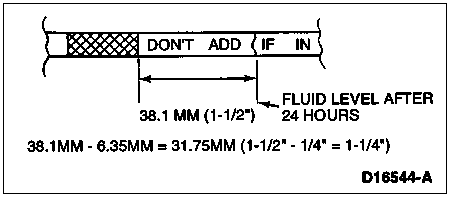
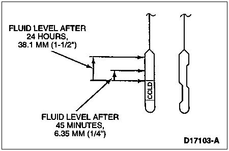
Allow the vehicle to sit for a minimum of 24 hours.
Check and note fluid level. Compare level to results in Step 3. If the fluid has risen 25.4mm (1 inch) or more above the level in the first check, excessive converter drainback has occurred.
If excessive converter drainback has occurred, replace drainback check valve at rear case fitting and repeat test.

Shift Linkage Check
Refer to Section 07-05.