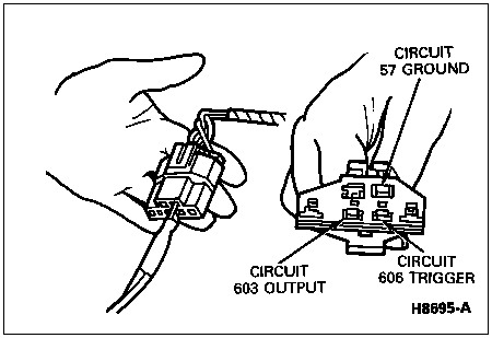
NOTE: Only one multi-pin connector is used.
Connect the tester connector to the vehicle data link connector.

Section 06-09B: Brake, Anti-Lock, 4-Wheel | 1996 Bronco Workshop Manual |
NOTE: For non-ABS brake system diagnosis, refer to Section 06-00.
Warning Lamp Indicators
The anti-lock brake system uses one amber ABS warning light to alert the driver of malfunctions in the system.
The amber ABS warning light will come on for numerous reasons. It warns the driver that the ABS has been disabled. Normal power-assisted braking remains but the wheels can lock during a panic stop while the indicator is on. Certain procedures must be followed to find the concern in this situation. They are explained in this section. If system is OK, Code 16 will be present.
On-Board Diagnostics
The anti-lock brake electronic control module monitors system operation and can store all defined service codes in its memory. It is important to understand that there are some concerns the anti-lock brake electronic control module cannot recognize. Therefore, if a symptom exists and no diagnostic trouble codes are stored by the anti-lock brake electronic control module, other diagnostic steps must be followed.
The anti-lock brake electronic control module cannot store a diagnostic trouble code if there is no power to the anti-lock brake electronic control module. This concern can be found by following the system precheck procedures.
Diagnostic Codes, Retrieving
The anti-lock brake electronic control module is capable of performing on-board diagnostics. To retrieve codes from the anti-lock brake electronic control module, the following techniques can be used:
New Generation Star Tester Technique
Turn the ignition switch (11572) to OFF.
Locate the tester data link connector in the engine compartment, labeled ANTI-LOCK TEST.
NOTE: Only one multi-pin connector is used.
Connect the tester connector to the vehicle data link connector.

When the tester hookup is complete, proceed with the on-board diagnostic procedure. If any diagnostic trouble codes appear during the on-board diagnostics, refer to the Symptom Chart.
Turn the key to RUN.
NOTE: Write down all codes. Code 16 indicates system OK. Do not replace anti-lock brake electronic control module.
Read the first code output; after approximately 15 seconds the next code will be output.
Light Flash Technique
NOTE: If 12V test light is not available, the amber ABS warning light also flashes during this test.
Locate test connector in the engine compartment and install 12V test light between Pins C and E.
With the ignition off, jumper Pin E to B.
Turn key to RUN position.
Remove jumper between Pins E and B after 5 seconds.
Count light flashes of test light or amber ABS warning light.
Breakout Box Setup
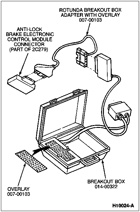
Disconnect the 40-pin plug from the anti-lock brake electronic control module.
Connect the Rotunda Breakout Box Adapter with Overlay 007-00103 or equivalent to the 40-pin plug on the vehicle harness.
Connect the adapter's 60-pin plug to the breakout box cable.
Install overlay.
Refer to pinpoint test procedures for specific servicing directions.

Diagnostic Trouble Codes, Erasing
The diagnostic trouble codes can be erased from the anti-lock brake electronic control module in the following manners.
Manually Clearing Diagnostic Codes
All diagnostic trouble codes must be output, all concerns corrected (anti-lock light off) and vehicle driven about 40 km/h (25 mph) before diagnostic trouble codes will be erased.
NOTE: Do not raise vehicle on hoist and accelerate to 40 km/h (25 mph) to simulate driving the vehicle. Erroneous sensor codes will be set.
Automatic Memory Erasing
A diagnostic trouble code will be automatically erased if no system concerns occur for 50 ignition cycles.