Section 06-05: Brake System, Parking
1996 Bronco, F-150, F-250, F-350, F-Super Duty Chassis Cab and Motorhome Chassis Vehicles Workshop Manual
DISASSEMBLY AND ASSEMBLY

Brake, Parking, Transmission-Mounted

SPECIAL SERVICE TOOL(S) REQUIRED
DescriptionTool Number
2 9/16-Inch Hex Locknut WrenchT70T-4252-D
Bearing Cup PullerT77F-1102-A
Bearing Cup ReplacerT88T-2598-E
Seal ReplacerT88T-2598-C
Bearing Cup ReplacerT88T-2598-D
Bearing Cone ReplacerT88T-2598-F
Seal ReplacerT88T-2598-B
 

Disassembly

  1. Remove the parking brake assembly from the vehicle. Refer to the procedure in this section.

    Parking Brake Assembly, Transmission-Mounted

    ItemPart NumberDescription
    1Parking Brake Drum
    (Part of 2C598)
    2Output Flange
    (Part of 2C598)
    32L611Mainshaft-to-Outut Flange Nut
    42L610Output Flange Plug
    52A710Actuating Lever
    62A703Splash Shield
    72L598Parking Brake Shoe and Backing Plate Assembly
    82L618Backing Plate-to-Housing Bolt
    92L617Mainshaft-to-Output Flange Bolt
    10Mainshaft (Part of 2C598)
    11Parking Brake Seal Disc (Part of 2C598)
    122M598Actuating Lever Spring
    132L605Parking Brake Vent
    142L606Parking Brake Rear Seal
    152L603Parking Brake Rear Bearing
    162L608Parking Brake Filler Plug
    172K598Parking Brake Housing
    182L613Mainshaft Shim
    192L602Parking Brake Front Bearing
    207288O-Ring
    212L601Mainshaft Spacer
    222L607Parking Brake Front Seal
    23Lock Nut Washer
    (Part of 2598)
    242L616Lock Nut
    ATighten to 113-117 Nm (84-86 Lb-Ft)
    BTighten to 118-123 Nm (87-90 Lb-Ft)
    CUnless Damaged, Leave Bolt in Mainshaft
    DUnless Damaged, Leave Seal Disc in Mainshaft
    ETighten to 11-16 Nm
    (8-12 Lb-Ft)
    FTighten to 35-40 Nm
    (26-29 Lb-Ft)
    GUse New Lock Nut and Tighten to 288-292 Nm (213-215 Lb-Ft)
  1. Remove the parking brake filler plug and drain the lubricant.

  1. Remove the parking brake vent.

  1. Mount the parking brake in a vise so that the vise jaws grip the output flange yoke.

  1. If required, use a hammer and punch to relieve the locking punch mark from the locknut flange so that the locknut can be freely turned.

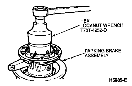
  1. Using 2 9/16-Inch Hex Locknut Wrench T70T-4252-D, remove the lock nut from the mainshaft.

  1. Remove the lock nut washer.

  1. Remove the parking brake from the vise.

  1. NOTE: Use care not to lose the mainshaft shim.

    Using 2-3 Jaw Puller D80L-1013-A or equivalent, separate the mainshaft, parking brake drum and output flange assembly from the parking brake housing.

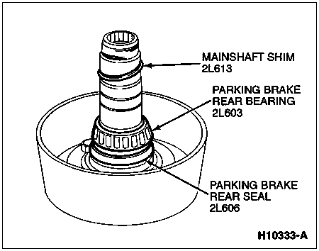
  1. Remove the mainshaft shim from the mainshaft.

  1.  CAUTION: The mainshaft, parking brake drum and output flange are factory balanced and serviced as an assembly only. Match mark and disassemble only if replacing the parking brake rear bearing or parking brake rear seal.

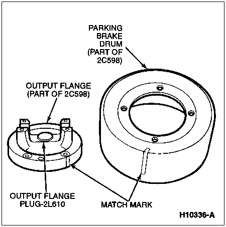
    Match mark the output flange, parking brake drum and mainshaft for assembly reference.

  1. Mount the mainshaft, parking brake drum and output flange assembly in vise gripping the output flange yoke.

  1.  CAUTION: To maintain factory balance, do not remove the mainshaft-to-output flange bolts from the mainshaft.

    Remove the four 11/16 mainshaft-to-output flange nuts.

  1. Remove the mainshaft and parking brake drum from the output flange.

  1. Remove the output flange from the vise.

  1. If damaged or leaking, remove the output flange plug from the center of the output flange.

  1. Using 2-3 Jaw Puller D80L-1013-A with Bearing Pulling Attachment D79L-4621-A and Step Plate D80L-630-6 or equivalents, remove the parking brake rear bearing from the mainshaft.

  1. Remove the parking brake rear seal from the mainshaft. Discard the seal.

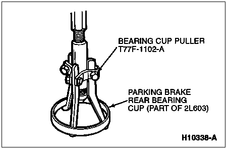
  1. NOTE: Insert the tool jaws into the recesses provided in the parking brake housing.

    Using Bearing Cup Puller T77F-1102-A, remove the parking brake rear bearing cup from the parking brake housing.

  1. Turn the parking brake housing over and remove the mainshaft spacer. Remove the O-ring from the spacer.

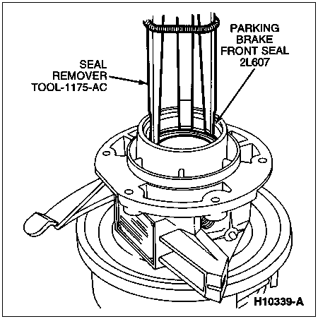
  1. Using Seal Remover TOOL-1175-AC or equivalent, remove the parking brake front seal. Discard the seal.

  1. Remove the parking brake front bearing cone from the parking brake housing.

  1. NOTE: Position the tool jaws in the recesses provided in the casting.

    Using Bearing Cup Puller T77F-1102-A or equivalent, remove the parking brake front bearing cup from the parking brake housing.

  1. Remove the four backing plate-to-parking brake housing bolts.

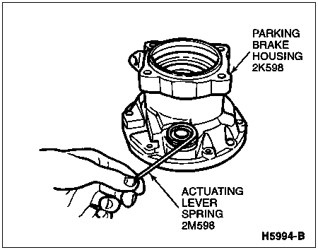
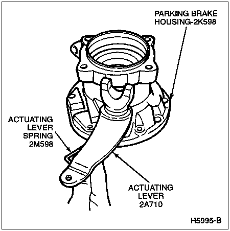
  1. NOTE: To aid assembly, observe the orientation of the actuating lever and actuating lever spring.

    NOTE: Because the parking brake shoes and the backing plate are serviced as a combined unit, they are not disassembled any further.

    Remove the parking brake shoe and backing plate assembly from the parking brake housing.

  1. Remove the splash shield from the parking brake housing.

  1. Remove the actuating lever and the actuating lever spring from the parking brake housing.


Assembly

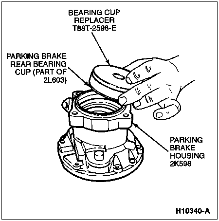
  1. Using Bearing Cup Replacer T88T-2598-E, install the parking brake rear bearing cup in the parking brake housing.

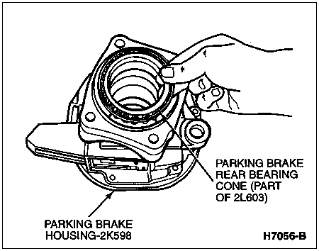
  1. Position the parking brake rear bearing cone in the parking brake rear bearing cup.

  1. NOTE: The lip of the parking brake rear seal should face inward.

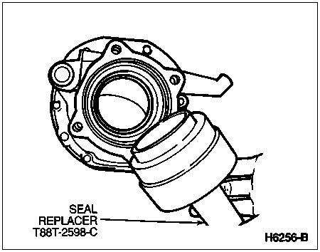
    Using Seal Replacer T88T-2598-C, install a new parking brake rear seal.

  1. Turn the parking brake housing over and, using Bearing Cup Replacer T88T-2598-D, install the parking brake front bearing cup.

  1. Using the orientation noted at disassembly, position the actuating lever spring on the parking brake housing.

  1. Apply a light coating of Ford Disc Brake Caliper Slide Grease D7AZ-19590-A or equivalent meeting Ford specification ESA-M1C172-A to the ball of the actuating lever.

  1. Position the actuating lever ball end through the coil of the actuating lever spring into the mating hole in the parking brake housing.

  1. Position the splash shield on the parking brake housing over the actuating lever cam.

  1. Position the parking brake shoe and backing plate assembly on the splash shield.

  1. Install the four backing plate-to-housing bolts through the backing plate and splash shield. Tighten to 118-123 Nm (87-90 lb-ft).

  1. Position the actuating lever spring on the actuating lever to apply tension.

  1.  CAUTION: Use soft jaws to protect the mainshaft.

    Mount the mainshaft in a suitable vise with the flange end upward.

  1. If necessary, apply sealer and install the output flange plug. Make sure the plug is flush with the output flange bore.

  1. Aligning the disassembly match marks, position the parking brake drum and output flange over the mainshaft-to-output flange bolts.

  1. Install, but do not tighten, the four 11/16 mainshaft-to-output flange nuts.

  1. Remove the mainshaft, parking brake drum and output flange assembly from the vise and reverse the position so that the vise clamps on the output flange yoke.

  1. Tighten the mainshaft-to-output flange nuts to 113-117 Nm (84-86 lb-ft).

  1.  CAUTION: Use care not to damage the parking brake rear bearing seal.

    Carefully guide the parking brake housing over the mainshaft.

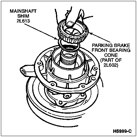
  1. NOTE: The mainshaft shim determines the mainshaft end play and is available in increments of 0.048mm (0.0019 inch).

    Install the mainshaft shim.

  1. Install the parking brake front bearing cone.

  1. Seat the front bearing cone, using Bearing Cone Replacer T88T-2598-F.

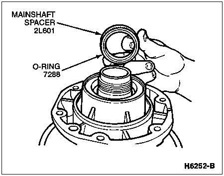
  1. NOTE: For mainshaft end play measurement, install the mainshaft spacer without the O-ring.

    Install the mainshaft spacer.

  1. Install the lock nut washer.

  1. Install a new lock nut and, using 2 9/16-Inch Hex Locknut Wrench T70T-4252-D, tighten to 288-292 Nm (213-215 lb-ft).

  1. Remove the parking brake from the vise and position on a smooth flat surface with the output flange down.

  1. Mount Dial Indicator with Bracketry TOOL-4201-C or equivalent between the mainshaft and the parking brake housing to check end play.

  1. While rotating the parking brake housing on the mainshaft to center the bearings, apply pressure up and down while taking an end play reading. A reading of 0.0483-0.0991mm (0.0019-0.0039 inches) is required. If the measurement is not within specification, a thinner or thicker shim will be required.

  1. Mount the parking brake in a vise, gripping the output flange yoke.

  1. Remove the lock nut, lock nut washer and mainshaft spacer from the mainshaft.

  1. NOTE: Use care not to lose the mainshaft shim.

    If required to install different size mainshaft shim, use 2-3 Jaw Puller D80L-1013-A or equivalent, to separate the mainshaft, parking brake drum and output flange assembly from the parking brake housing only enough to free the parking brake front bearing cone.

  1. If required, remove the parking brake front bearing cone and install the mainshaft shim required to meet end play specification.

  1. If required, reinstall the parking brake front bearing cone.

  1. If required, seat the front bearing cone using Bearing Cone Replacer T88T-2598-F.

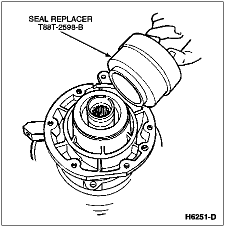
  1. NOTE: The lip of the parking brake front seal must face inward.

    Using Seal Replacer T88T-2598-B, install a new parking brake front seal.

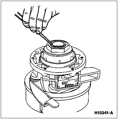
  1. Install a new O-ring in the groove of the mainshaft spacer.

  1. Install the mainshaft spacer on the mainshaft up to the inner race of the parking brake front bearing.

  1. Install the lock nut washer, the lock nut and, using 2 9/16-Inch Hex Locknut Wrench T70T-4252-D, tighten to 288-292 Nm (213-215 lb-ft).

  1. Use a hammer and punch to dimple the lock nut flange into the notch on the mainshaft.

  1. NOTE: The parking brake vent must be clean and open.

    Install the parking brake vent. Tighten to 11-16 Nm (8-12 lb-ft).

  1. Remove the parking brake from the vise.

  1. Install the parking brake on the vehicle. Refer to the procedure in this section.

  1. Fill the parking brake to the bottom of the filler hole with Motorcraft MERCON® Multi-Purpose Automatic Transmission Fluid, XT-2-QDX or DDX or MERCON® equivalent.

  1. Install the parking brake filler plug. Tighten to 35-40 Nm (26-29 lb-ft).