Section 06-05: Brake System, Parking | 1996 Bronco, F-150, F-250, F-350, F-Super Duty Chassis Cab and Motorhome Chassis Vehicles Workshop Manual |
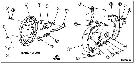
Rear Brake Shoe and Lining, Disassembled

| Item | Part Number | Description |
|---|---|---|
| 1 | 20310-S | Rear Wheel Cylinder Retaining Bolt (2 Req'd) |
| 2 | 34941-S | Washer |
| 3 | 2211 | Brake Backing Plate |
| 4 | 2028 | Brake Shoe Anchor Pin Guide Plate |
| 5 | 2261 | Rear Wheel Cylinder |
| 6 | 2042 | Wheel Cylinder Brake Shoe Link |
| 7 | 2A642 | Primary Brake Shoe Parking Brake Lever Link |
| 8 | 2A637 | Parking Brake Lever |
| 9 | 2200 | Secondary Shoe Assembly |
| 10 | 351467-S | Washer |
| 11 | 2106 | Parking Brake Lever Pin Retainer |
| 12 | 2A179 | Cable Guide |
| 13 | 2A176 | Brake Shoe Adjusting Lever |
| 14 | 2048 | Socket |
| 15 | 372583-S | Washer |
| 16 | 2041 | Brake Adjuster Screw |
| 17 | 2047 | Brake Shoe Adjusting Screw Nut |
| 18 | 2066 | Brake Shoe Hold-Down Spring Cup |
| 19 | 2068 | Brake Shoe Hold-Down Spring |
| 20 | 2200 | Primary Shoe Assembly |
| 21 | 2049 | Brake Shoe Adjusting Screw Spring |
| 22 | 2A178 | Brake Shoe Adjusting Lever Cable |
| 23 | 2035 | Brake Shoe Retracting Spring |
| 24 | 2A601 | Parking Brake Link Spring |
| 25 | 2A787 | Retainer (Parking Brake Spring) |
| 26 | 2069 | Brake Shoe Hold-Down Spring Pin |
| 27 | 2092 | Brake Adjusting Hole Cover |
Removal
Remove the LH cowl side panel (02038).
To gain the needed slack, have an assistant pull the intermediate cable toward the rear of the vehicle.
While the assistant holds the intermediate cable, insert a 4mm (0.156 in.) pin into the hole provided in the parking brake control (2780).

![]() WARNING: DO NOT INHALE DUST FROM BRAKES OR ASSOCIATED COMPONENTS. INHALATION OF DUST CAN BE HAZARDOUS TO YOUR HEALTH. COMPRESSED AIR OR BRUSHES MUST NOT BE USED TO CLEAN BRAKES, BRAKE DRUMS (1126) AND ASSOCIATED COMPONENTS. A VACUUM CLEANER (ROTUNDA BRAKE/CLUTCH/SERVICE VACUUM 164-R3600 OR EQUIVALENT) EQUIPPED FOR THIS PURPOSE SHOULD BE CAREFULLY USED TO REMOVE ANY DUST. ADHERENT DUST SHOULD BE REMOVED WITH A DAMP RAG. ANY DUST SHOULD BE CONTAINED IN A SEALED AND LABELED BAG FOR DISPOSAL. WEAR AN APPROVED HIGH EFFICIENCY CARTRIDGE OR AIR LINE RESPIRATOR AND USE EXTRA CAUTION TO AVOID BREATHING THIS DUST.
WARNING: DO NOT INHALE DUST FROM BRAKES OR ASSOCIATED COMPONENTS. INHALATION OF DUST CAN BE HAZARDOUS TO YOUR HEALTH. COMPRESSED AIR OR BRUSHES MUST NOT BE USED TO CLEAN BRAKES, BRAKE DRUMS (1126) AND ASSOCIATED COMPONENTS. A VACUUM CLEANER (ROTUNDA BRAKE/CLUTCH/SERVICE VACUUM 164-R3600 OR EQUIVALENT) EQUIPPED FOR THIS PURPOSE SHOULD BE CAREFULLY USED TO REMOVE ANY DUST. ADHERENT DUST SHOULD BE REMOVED WITH A DAMP RAG. ANY DUST SHOULD BE CONTAINED IN A SEALED AND LABELED BAG FOR DISPOSAL. WEAR AN APPROVED HIGH EFFICIENCY CARTRIDGE OR AIR LINE RESPIRATOR AND USE EXTRA CAUTION TO AVOID BREATHING THIS DUST.
Remove the wheel (1007) and brake drum.
Pull back the boots of the rear wheel cylinder (2261) and inspect for signs of leakage. Rear wheel cylinders that show evidence of leakage (water getting in past the boots or brake fluid leaking out) must be removed and repaired or replaced. Refer to Section 06-02.
If no leaks are found, install a brake cylinder clamp over the ends of the rear wheel cylinders.
Contract the rear brake shoes and linings (2200) as follows:
![]() CAUTION: Note the color and position of each brake shoe adjusting screw spring (2049). They must be reassembled in same position.
CAUTION: Note the color and position of each brake shoe adjusting screw spring (2049). They must be reassembled in same position.
Pull the brake shoe adjusting lever, brake shoe adjusting lever cable and brake shoe adjusting screw spring down and toward the rear to unhook the pivot hook from the large hole in the web of the rear brake shoe and lining. Do not pry the pivot hook out of the hole.
Remove the brake shoe adjusting screw spring and brake shoe adjusting lever.
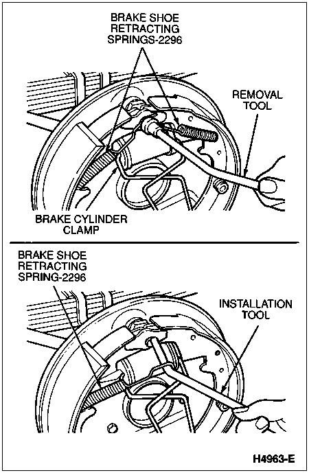
Remove the secondary brake shoe retracting spring (2296) using a brake spring removal/installation tool. Using the same tool, remove the primary brake shoe retracting spring and unhook the cable anchor. Remove the brake shoe anchor pin guide plate (2028) (if equipped).
Remove the cable guide from the rear brake shoe and lining.
NOTE: Note the color and position of each brake shoe hold-down spring (2068). They must be reassembled in the same position.
Remove the brake shoe hold-down springs, rear brake shoes and linings, brake adjuster screw, pivot nut, and brake shoe adjusting screw socket (2048).
Remove the primary brake shoe parking brake lever link (2A642) and parking brake link spring (2A601). Disconnect the front parking brake cable and conduit (2853) from the parking brake lever (2A637).
Remove the secondary rear brake shoe and lining and disassemble the parking brake lever from the rear brake shoe and lining by removing the parking brake lever pin retainer (2106) and spring washer.
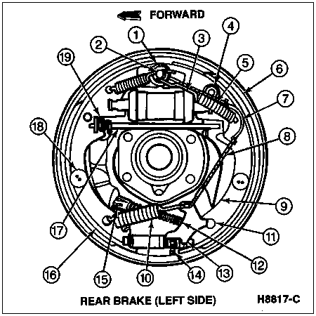
Spring Replacement, Typical

Self-Adjusting Brake Assemblies, Rear, Standard, F-150 and Bronco

| Item | Part Number | Description |
|---|---|---|
| 1 | 2028 | Brake Shoe Anchor Pin Guide Plate |
| 2 | — | Anchor Pin (Part of 2211) |
| 3 | 2261 | Rear Wheel Cylinder |
| 4 | 351467-S | Washer |
| 5 | 2296 | Brake Shoe Retracting Spring |
| 6 | 2200 | Rear Brake Shoe and Lining, Secondary |
| 7 | 2A179 | Cable Guide |
| 8 | 2A178 | Brake Shoe Adjusting Lever Cable |
| 9 | 2A637 | Parking Brake Lever |
| 10 | 2049 | Brake Shoe Adjusting Screw Spring |
| 11 | — | Pivot Hook (Part of 2A176) |
| 12 | 2A635 | Parking Brake Rear Cable and Conduit |
| 13 | 2A176 | Brake Shoe Adjusting Lever |
| 14 | 2041 | Brake Adjuster Screw |
| 15 | — | Parking Brake Cable Housing Retainer (Part of 2A635) |
| 16 | 2200 | Rear Brake Shoe and Lining, Primary |
| 17 | 2A642 | Primary Brake Shoe Parking Brake Lever Link |
| 18 | 2068 | Brake Shoe Hold-Down Spring |
| 19 | 2A601 | Parking Brake Link Spring |
Installation
Clean the ledge pads on the brake backing plate (2211). Sand lightly to bare metal.
Apply a light coating of high temperature lithium-base grease such as Premium Long-Life Grease XG-1-C or -K or equivalent meeting Ford specification ESA-M1C75-B or Disc Brake Caliper Slide Grease D7AZ-19590-A or equivalent meeting Ford specification ESA-M1C172-A at the points where the rear brake shoes and linings touch the brake backing plate. Also lubricate the adjusting cable eye and the anchor pin area.
Before installing the rear brake shoes and linings, assemble the parking brake lever on the rear brake shoes and linings and secure with the spring washer and parking brake lever pin retainer.
Position the rear brake shoes and linings on the brake backing plate, and install the brake shoe hold-down spring pins (2069), brake shoe hold-down springs, and brake shoe hold-down spring cups (2066).
Install the primary brake shoe parking brake lever link, parking brake link spring and washer.
Connect the parking brake cable to the parking brake lever.
Install the brake shoe anchor pin guide plate, if equipped, and place the cable anchor over the anchor pin with the crimped side toward the brake backing plate.
Install the primary brake shoe retracting spring using a brake spring removal/installation tool.
![]() CAUTION: Make sure the brake shoe adjusting lever cable is positioned in the groove, and not between the guide and the web of the rear brake shoe and lining.
CAUTION: Make sure the brake shoe adjusting lever cable is positioned in the groove, and not between the guide and the web of the rear brake shoe and lining.
Install the cable guide on the secondary rear brake shoe and lining with the flanged hole fitted into the hole in the secondary rear brake shoe and lining.
Thread the brake shoe adjusting lever cable around the cable guide groove.
![]() CAUTION: Install the brake adjuster screw in the same location from which it was removed. Interchanging the brake adjuster screws from one side of the vehicle to the other will cause the rear brake shoes and linings to retract rather than expand each time the automatic adjusting mechanism is operated.
CAUTION: Install the brake adjuster screw in the same location from which it was removed. Interchanging the brake adjuster screws from one side of the vehicle to the other will cause the rear brake shoes and linings to retract rather than expand each time the automatic adjusting mechanism is operated.
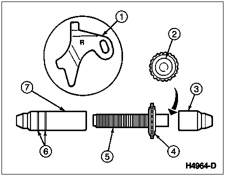
NOTE: To prevent incorrect installation, the socket end of each brake adjuster screw is stamped with R or L to indicate their installation on the right or left side of the vehicle. The brake shoe adjusting screw nuts (2047) can be distinguished by the number of lines machined around the body of the brake shoe adjusting screw nut. Two lines indicate a right-hand brake shoe adjusting screw nut; one line indicates a left-hand brake shoe adjusting screw nut.
NOTE: Another way to identify brake adjuster screws is to check thread pitch. The right side brake adjuster screw has right-hand threads while the left side brake adjuster screw has left-hand threads. The brake adjuster screw will also increase in length when the lever is operated, if properly installed.
Install the secondary (long) brake shoe retracting spring. Make sure the cable end is not cocked or binding on the anchor pin when installed. All parts should be flat on the anchor pin. Remove the brake cylinder clamp.
Apply Disc Brake Caliper Slide Grease D7AZ-19590-A or equivalent meeting Ford specification ESA-M1C172-A to the threads and the socket end of the brake adjuster screw. Turn the brake shoe adjusting screw into the brake shoe adjusting screw nut to the end of the threads and then loosen it one-half turn.
Place the brake shoe adjusting screw socket on the brake adjuster screw and install the assembly between the ends of the rear brake shoes and linings with the brake adjuster screw nearest the secondary brake shoe adjusting screw nut.
Hook the cable hook into the hole in the brake shoe adjusting lever from the outboard plate side. The brake shoe adjusting levers are also stamped with an R or L to indicate their installation on the right- or left-hand brake.
Brake Adjuster Screw and Brake Shoe Adjusting Lever Kit, Rear, F-150 and Bronco

| Item | Part Number | Description |
|---|---|---|
| 1 | 2A176 | Brake Shoe Adjusting Lever |
| 2 | 372583-S | Washer |
| 3 | 2048 | Brake Shoe Adjusting Screw Socket |
| 4 | — | Knurled Nut (Part of 2041) |
| 5 | 2041 | Brake Adjuster Screw |
| 6 | — | Identification Lines (Part of 2047) |
| 7 | 2047 | Brake Shoe Adjusting Screw Nut |
Place the hooked end of the brake shoe adjusting screw spring in the large hole in the web of the primary rear brake shoe and lining. Connect the loop end of the brake shoe adjusting screw spring to the hole of the brake shoe adjusting lever.
Pull the brake shoe adjusting lever, brake shoe adjusting lever cable and brake shoe adjusting screw spring down toward the rear to engage the pivot hook in the large hole in the web of the secondary rear brake shoe and lining.
Check the action of brake adjuster screw by pulling brake shoe adjusting lever cable toward secondary rear brake shoe and lining, activating brake shoe adjusting lever. Brake shoe adjusting levers should snap in behind the next tooth of brake adjuster screw. Release brake shoe adjusting lever cable to return brake shoe adjusting lever to original position and the brake adjuster screw should turn one notch.
If pulling the brake shoe adjusting lever cable does not produce the action described, or if lever action is sluggish instead of positive and sharp, check the position of the lever on the adjusting screw toothed wheel. With the brake in a vertical position (anchor at the top), the lever should contact the adjusting wheel one tooth above the centerline of the adjusting screw. If the contact point is below this centerline, the lever will not lock on the teeth in the adjusting screw wheel, and the screw will not be turned as the lever is actuated by the cable.
Install the brake drum and wheel.
Restore parking brake cable tension by pulling the pin inserted into the parking brake control.

Check parking brake operation.
Test brake system for normal operation.