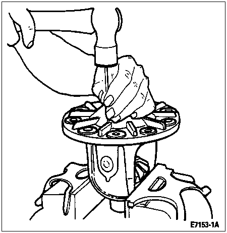
Use a small drift to remove the differential pinion shaft lock pin (4241) retaining the differential pinion shaft (4211).
Section 05-03D: Differential, Front Drive, Dana Model 44 Limited Slip | 1996 F-150 4x4 Front Axle Vehicles Workshop Manual |
When axle lubricant has been drained for front axle repair (limited slip only), refill the axle with the specified quantity of 4x4 Gear Oil F1TZ-19580-A (WSL-M2C191-A) and add 0.089L (3 ounces) of Ford Friction Modifier F3TZ-19B546-MA or equivalent friction modifier meeting Ford specification WSP-M2C-196-A.
NOTE: 4x4 Gear Oil F1TZ-19580-A (WSL-M2C191-A) is used in all IFS model axles. F1TZ-19580-A (WSL-M2C191-A) has no equivalent. DO NOT USE ANYTHING ELSE.
| Description | Tool Number |
|---|---|
| Limited Slip Differential Tool Includes: | T83T-4205-A |
| Step Plate | T83T-4205-A4 |
| Forcing Nut | T83T-4205-A2 |
| Forcing Screw | T83T-4205-A3 |
| Driver Handle | T83T-4205-A1 |
Disassembly
It is not necessary to remove the differential bearings (4221) to overhaul the limited slip differential (4026); however, the ring gear will have to be removed first.
To remove and install the differential side gears (4236), differential pinion gears (4215), differential pinion thrust washers (4230) and differential clutch packs during disassembly and assembly requires special procedures and tooling.
NOTE: An axle shaft (4234) placed in a vise, with the splines extending not more than three inches above the jaws of the vise, makes an excellent holding fixture after the differential case (4204) has been removed from the left axle support arm.
Place a few shop towels over the vise to prevent the ring gear teeth from being nicked. Remove the ring gear bolts. Tap the ring gear with a rawhide hammer to free it from the differential case. Remove the ring gear from the vise.
Use a small drift to remove the differential pinion shaft lock pin (4241) retaining the differential pinion shaft (4211).

Remove the differential pinion shaft with a hammer and drift.
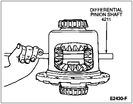
Position the Step Plate T83T-4205-A4 into the bottom differential side gear. Apply grease to the centering hole of the step plate.
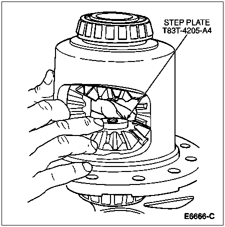
Install Forcing Nut T83T-4205-A2 and Forcing Screw T83T-4205-A3 into the differential case.
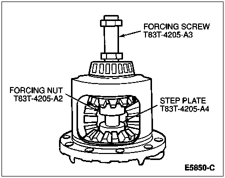
Guide the forcing screw onto the step plate.
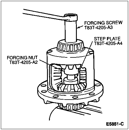
Tighten the forcing screw to move the differential side gears away from the differential pinion gears and relieve the normal loaded condition.
Using a piece of 0.762mm (0.030 inch) thick shim or gauge stock, push out the differential pinion thrust washers located behind the differential pinion gears.
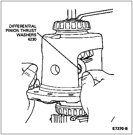
NOTE: The following step is very important to relieve the pressure of the differential clutch pack.
Momentarily, loosen the forcing screw.
NOTE: When attempting to rotate the differential side gear, some tightening or loosening of the forcing screw will probably be required to permit gear movement.
Retighten the forcing screw until a very slight movement of the differential pinion gears is seen.
Insert Driver Handle T83T-4205-A1 into the bore of the differential pinion shaft and rotate the differential case. Continue this until the differential pinion gears can be removed through the large openings in the differential case.
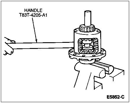
Retain the top differential side gear and differential clutch pack in the differential case by hand and remove the forcing screw.
Continue to hold the differential side gear and differential clutch pack and remove the gear rotating tool.
Remove the top differential side gear and differential clutch pack. Keep the stack of clutch plates and clutch discs in exact order.

Turn differential case so the flange or ring gear side is up. Ease the step plate, differential side gear and differential clutch pack out of the differential case.
Remove the retainer clips from both differential clutch packs to allow separation of the clutch discs and clutch plates for cleaning and inspection.
Inspect the clutch plates and clutch discs for cracks, excessive wear, and distortion. If one or more of the clutch plates or clutch discs needs replacing, replace entire stack of clutch plates. Inspect all other parts and replace any worn or damaged part.
Inspect the surfaces of the differential pinion shaft and the ramp surfaces on the differential case for excessive wear or pitting.
Inspect the teeth on the differential side gears and differential pinion gears.
Assembly
NOTE: Always replace the entire rear axle disc and plate kits (4880) even if only one component requires it.
Refer to illustrations used during disassembly for guidance in assembly operations.
Install the differential clutch packs, differential side gears and differential pinion thrust washers. Assemble in exactly the same order.
Prelubricate the thrust face of the differential side gears and assemble the clutch plates and clutch discs to the splines of the differential side gears, prelubricating each part with 4x4 Gear Oil F1TZ-19580-A (WSL-M2C191-A) or with Ford Friction Modifier F3TZ-19B546-MA or equivalent friction modifier lubricant meeting Ford specification WSP-M2C196-A, both stacks.
Assemble the retainer clips to the ears of the clutch plates. Make sure both clips are completely assembled or seated onto the ears of the clutch plates.
NOTE: To prevent the differential clutch pack from falling out of the differential case, hold in place by hand while repositioning the differential case on a bench.
Assemble the differential clutch pack and differential side gear into the differential case. Make sure the differential clutch pack stays assembled to the splines of differential side gear, and the retainer clips are completely seated into the pockets of the differential case.
Reposition the differential case on the bench. Assemble the Step Plate T83T-4205-A4 into bottom side gear bore. Apply a small amount of Premium Long-Life Grease XG-1-C or -K or equivalent meeting Ford specification ESA-M1C75-B into the centering hole of the step plate.
Assemble the other differential clutch pack and differential side gear. Make sure the differential clutch pack stays assembled to the splines of the differential side gear, and the retainer clips are completely seated into the pockets of the differential case.
Install Forcing Nut T83T-4205-A2 to top of the differential side gear.
Hold the differential side gear in position by hand. Insert Forcing Screw T83T-4205-A3 down through the top of the differential case, and thread forcing nut on the screw. The tip of the forcing screw must contact the step plate.
With tools assembled to the differential case, position the differential case onto the axle shaft (as a holding fixture) by aligning the splines of the differential side gear with those of the axle shaft.
Position both differential pinion gears opposite one another through the openings in the differential case. Align holes of the differential pinion gears with each other. Hold the differential pinion gears in place by hand.
Tighten the forcing screw so the differential side gears move away from the differential pinion gears and relieve the loaded condition.
While holding the differential pinion gears in place, insert Handle T83T-4205-A1 into the hole of differential pinion shaft in the differential case. Pull on the handle rotating differential case allowing the differential pinion gears to rotate and enter into the differential case.
Adjust the forcing screw by very slightly loosening or tightening until the required load is applied to allow the differential side gears and differential pinion gears to rotate.
Rotate the differential case until the holes of both differential pinion gears are aligned with those of the differential case.
Prelubricate both sides of the differential pinion thrust washers with the specified lubricant, 4x4 Gear Oil F1TZ-19580-A meeting Ford specification WSL-M2C191-A.
![]() CAUTION: Do not overtighten the forcing screw. Overtightening the forcing screw may damage the differential clutch pack.
CAUTION: Do not overtighten the forcing screw. Overtightening the forcing screw may damage the differential clutch pack.
Apply torque to the forcing screw for clearance to assemble the differential pinion thrust washers.
NOTE: During assembly, be sure the holes of the differential pinion thrust washers and differential pinion gears are lined up exactly with those of the differential case.
Assemble differential pinion thrust washers into the differential case. Use a very small screwdriver to push the washers into place.
Remove the forcing screw, forcing nut, handle, and step plate.
Install the differential pinion shaft in the differential case. Install the differential pinion shaft lock pin.
Install the ring gear to the differential case. Tighten new attaching bolts to 95-122 Nm (70-90 lb-ft).