Certain types of gear tooth contact patterns on the ring gear indicate incorrect adjustment. Incorrect adjustment can be corrected by readjusting the ring gear or the pinion.
Tooth Patterns

Section 05-03B: Axle, Front Drive, Dana Model 60 Monobeam | 1996 F-350 4x4 Workshop Manual |
When rolling a tooth pattern, use a special marking compound (tube) to obtain gear tooth mesh contact pattern.
NOTE: A marking compound mixture that is too wet will run and smear; too dry a mixture cannot be pressed out from between the teeth.
To check the gear tooth contact, paint the gear teeth with the special marking compound.
Rotate ring gear (use a box wrench on the ring gear attaching bolts as a lever) several complete revolutions in both directions or until a clear tooth contact pattern is obtained.
Certain types of gear tooth contact patterns on the ring gear indicate incorrect adjustment. Incorrect adjustment can be corrected by readjusting the ring gear or the pinion.

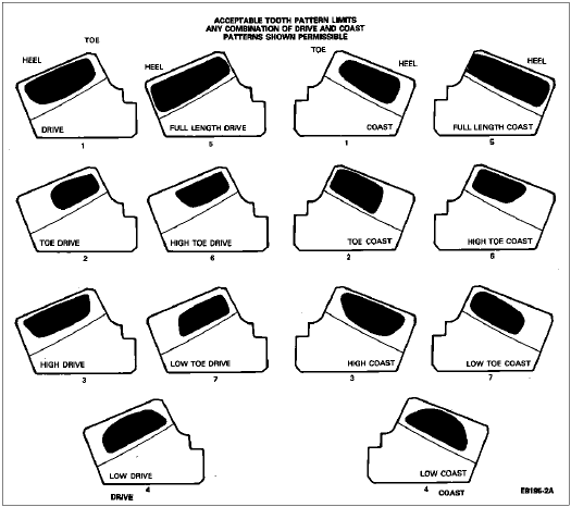
The previous illustration shows acceptable tooth patterns for all axles. In general, desirable tooth patterns should have the following characteristics:
An individual gear set need not conform exactly to the ideal pattern to be acceptable. Any combination of drive and coast patterns shown is acceptable.

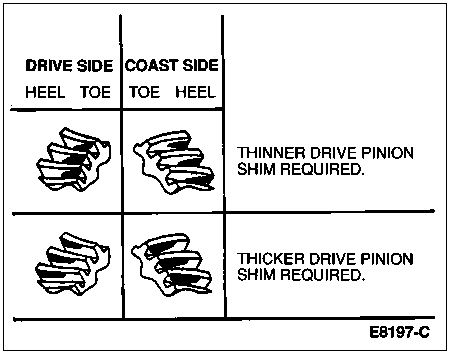
NOTE: When making pinion position changes, drive pinion shims should be changed in the range of 0.05mm (0.002 inch) to 0.10mm (0.004 inch) until correct pattern has been obtained.
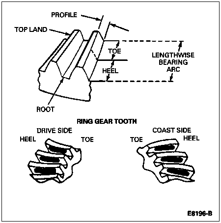
Since each gear set rolls a characteristic pattern, the patterns shown are considered acceptable and should be used as a guide. The drive pattern is rolled on the convex side of the tooth, and the coast pattern is rolled on the concave side.
The movement of tooth contact patterns with changes in shimming can be summarized as follows:

NOTE: If the patterns are not correct, make the changes as indicated. The differential case (4204) and drive pinion will have to be removed from the carrier housing to change a differential bearing shim (4067).
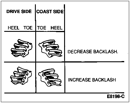
If the drive pinion shims are correct, decreasing backlash moves the ring gear closer to the pinion. Drive pattern (convex side of gear) moves slightly lower and toward the toe. Coast pattern (concave side of gear) moves lower and toward the toe. Increasing backlash moves the ring gear away from the pinion. Drive pattern moves slightly higher and toward the heel. Coast pattern moves higher and towards the heel.

NOTE: Backlash tolerance is 0.13-0.23mm (0.005-0.009 inch) and cannot vary more than 0.08mm (0.003 inch) between the three points.
NOTE: When a change in backlash is required, differential bearing shims should be changed in the range of 1-1/2 times the amount of backlash required to bring the gears into specification. For example, if the backlash needed to be changed by 0.10mm (0.004 inch), the differential bearing shims should be changed by 0.15mm (0.006 inch) as a starting point. The actual amount of backlash change obtained will vary depending upon the ratio and gear size.
Check ring gear backlash by installing a dial indicator on the carrier housing. Check ring gear and pinion backlash at three equally spaced points on the ring gear.
If backlash is high, the ring gear must be moved closer to the pinion, by moving differential bearing shims from the drive pinion side of the differential case to the ring gear side. If backlash is low, the ring gear must be moved away from the pinion by moving differential bearing shims from the ring gear side to the opposite side.