Section 05-03B: Axle, Front Drive, Dana Model 60 Monobeam
1996 F-350 4x4 Workshop Manual
REMOVAL AND INSTALLATION

Axle, Front

 
SPECIAL SERVICE TOOL(S) REQUIRED
DescriptionTool Number
Pitman Arm PullerT64P-3590-F


Removal

  1. Raise the vehicle on a twin-post hoist.

  1. Remove the front wheels (1007) and tires from the vehicle.

  1.  CAUTION: After removal, the disc brake caliper (2B120) must be wired to the spring or otherwise supported to prevent suspending the disc brake caliper by the flexible hose. Allowing the disc brake caliper to hang by the flexible hose could result in brake line failure. If suspension of the disc brake caliper is not practical, remove it. Refer to Section 06-03.

    Remove the disc brake caliper from the spindle. Refer to Section 06-03.
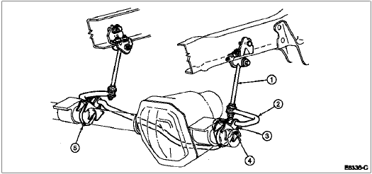
  1. Remove the washers and nuts securing the front stabilizer bar links (5K483) to the front stabilizer bar (5482). Disconnect the front stabilizer bar links from the front stabilizer bar.

  1. If required, remove the U-bolts and bolts and nuts retaining the front stabilizer bar and stabilizer bar brackets (5486) to the axle and remove the front stabilizer bar.


    Front Stabilizer Bar Assembly


    ItemPart NumberDescription
    15K483Front Stabilizer Bar Link
    25482Front Stabilizer Bar
    35486Stabilizer Bar Bracket
    4N606088-SBolt
    55455U-Bolt
  1. Remove the cotter pins and castellated nuts securing the connecting rod and tie rod end to the steering knuckles. Separate the connecting rod and tie rod end from the steering knuckles using Pitman Arm Puller T64P-3590-F. Wire the steering linkage to the spring.


    Spindle (Steering Knuckle) Connecting Rod Attachment Locations


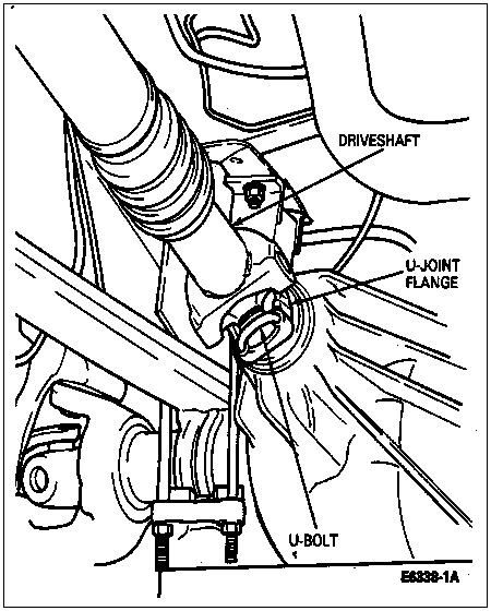
  1. Remove the two nuts and U-bolts from the front driveshaft U-joint flange.

  1. NOTE: Mark yoke and driveshaft with a marking paint pen for assembly in the same position.

    Disconnect the driveshaft from the front axle pinion flange. Securely wire the driveshaft to the frame.


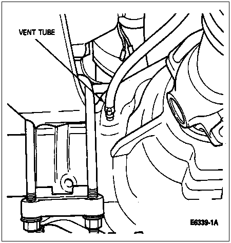
  1. Disconnect the vent tube at the axle housing. Plug the vent fitting.


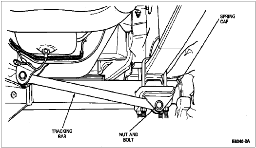
  1. On the right-hand side of the vehicle, remove the nut and bolt, and disconnect the tracking bar from the right-hand spring cap.


    Tracking Bar


  1. Carefully lower the twin-post hoist until the vehicle is approximately three feet from the floor.

  1.  WARNING: BEFORE PROCEEDING, MAKE SURE THAT THE VEHICLE IS SECURELY SUPPORTED.

    Position safety stands on the front springs about halfway between the front axle and the rear mounting shackle. Lower the vehicle so the front springs rest on the safety stands.

  1. Support the axle under the differential carrier with a suitable jack, such as Rotunda Heavy Duty Truck Transmission Jack 164-R3510 or equivalent.

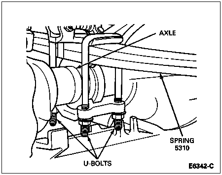
  1. Remove the U-bolts and nuts securing the axle to the spring.

  1. Carefully lower the axle from the vehicle.

  1. If required, place the axle in a suitable differential carrier repair stand.


Installation

  1. With the axle supported under the differential carrier by a suitable transmission jack, carefully raise the axle to the vehicle. Make sure that the retaining bolt head protruding from the leaf spring plate seats in the recessed portion of the axle spring mounting plate.

  1. Install the nuts, U-bolts and spring caps securing the axle to the front spring. Tighten to 113-153 Nm (83-113 lb-ft).

  1. Remove jack and raise the vehicle to a suitable working height. Remove safety stands.


    ItemPart NumberDescription
    1N801485-S56Bolt
    25A500Spacer
    3N801342-S2Nut
    45310Spring
    ATighten to 113-153 Nm
    (83-113 Lb-Ft)
  1. Connect the driveshaft to the front axle pinion flange, secure with nuts and U-bolts and tighten to 11-20 Nm (8-15 lb-ft). Refer to Section 05-01.

  1. On the right-hand side of the vehicle, connect the tracking bar to the spring cap, secure with nut and bolt. Tighten to 70-100 Nm (52-74 lb-ft).

  1. Connect the vent tube to the axle housing.

  1. Connect the connecting rod and tie rod end to the steering knuckles. Secure the connecting rod end and tie rod end with castellated nuts. Tighten to 70-100 Nm (52-74 lb-ft). Install cotter pins. If necessary, advance nut to next castellation to install cotter pin.

  1. Connect front stabilizer bar link to front stabilizer bar. Tighten to 21-33 Nm (15-24 lb-ft).

  1. If removed, position front stabilizer bar and stabilizer bar bracket on axle shaft housing and tighten nuts to 48-68 Nm (35-50 lb-ft).


    ItemPart NumberDescription
    15K483Front Stabilizer Bar Link
    25493Lower Suspension Arm Stabilizer Bar Insulator
    35486Stabilizer Bar Bracket
    45482Front Stabilizer Bar
    55455U-Bolt (RH)
    63002Axle Shaft Housing
    75484Rack and Pinion Mounting Bracket Insulator
    818171Washers
    9N805537-S100Bolt and Retainer
  1. Install disc brake calipers and part of front disc brake hub and rotors (1102). Refer to Section 06-03.

  1. Install the wheel and tire on the vehicle. Refer to Section 04-04.

  1. Check and fill axle lubricant.

  1. Lower the vehicle to the ground.