Section 05-03A: Axle, Front Drive, Dana Models 44 and 50
1996 F-150, F-250 4x4 and Bronco Workshop Manual
REMOVAL AND INSTALLATION

Slip-Yoke, RH, and Stub Shaft Assembly, Carrier, Carrier Oil Seal and Bearing

 
SPECIAL SERVICE TOOL(S) REQUIRED
DescriptionTool Number
Bench Mounted Holding FixtureT57L-500-B
Differential Housing Spreader AdaptersT80T-4000-B
Impact Slide HammerT50T-100-A
Needle Bearing ReplacerT83T-1244-A
Driver HandleT80T-4000-W


Removal

  1. Remove the nuts and U-bolts connecting the driveshaft to the yoke. Disconnect the driveshaft from the yoke. Wire the driveshaft out of the way, so it will not interfere in the carrier removal process.


    RH Slip-Yoke and Stub Shaft Assembly, Carrier, Carrier Oil Seal and Bearing
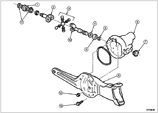


    ItemPart NumberDescription
    13A429Boot
    23L387Slip-Yoke
    33249Universal Joint
    43C123Seal
    53167C-Clip
    63010Carrier
    73254Seal
    83B403Left Axle Arm
    93254Needle Bearing
    103N387Stub
    113B478Keystone Clamps
    12358035-SFill Plug
    133C323Bolt
  1. Remove both front wheel spindles (3105) and the left and right shaft and U-joint assemblies. Refer to Spindle, RH and LH Shaft and U-Joint Assembly in the Removal and Installation portion of this section.

  1. Disconnect the vent tube and discard the hose clamps. Remove the vent fitting and install a 3mm (1/8-inch) pipe plug.

  1. NOTE: When performing the next step, position a drain pan under the carrier assembly to catch the lubricant when the carrier is separated from the arm.

    Support the carrier with a suitable jack and remove the bolts retaining the carrier to the support arm.

  1. Separate the carrier from the support arm. Remove the carrier from the vehicle.

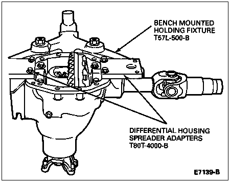
  1. Place the carrier in Bench Mounted Holding Fixture T57L-500-B and Differential Housing Spreader Adapters T80T-4000-B.


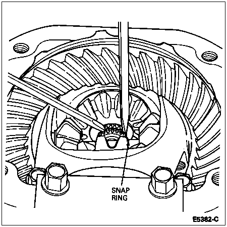
  1. Rotate the slip-yoke and shaft assembly so the open side of the snap ring is exposed as shown. Remove the snap ring from the shaft.


  1. Remove the slip-yoke and shaft assembly from the carrier.

  1. Remove the oil seal and caged needle bearings at the same time, using Impact Slide Hammer T50T-100-A and Collet (part of Blind Hole Puller Set D80L-100-A or equivalent) as shown. Discard the seal and needle bearing.


Installation

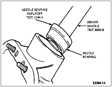
  1. Make sure the bearing bore is free from nicks and burrs. Install a new caged needle bearing on Needle Bearing Replacer T83T-1244-A with the manufacturer name and part number facing outward toward the tool. Drive the needle bearing until it is seated in the bore using Driver Handle T80T-4000-W.


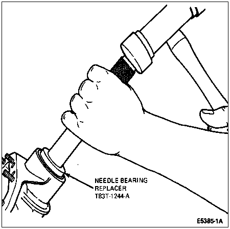
  1. Coat the seal with High Temperature 4x4 Front Axle and Wheel Bearing Grease E8TZ-19590-A or equivalent meeting Ford specification ESA-M1C198-A. Drive the seal into the carrier using Needle Bearing Replacer T83T-1244-A.


  1. Install the slip-yoke and shaft assembly into the carrier so the groove in the shaft is visible in the differential case.

  1. NOTE: Do not tap on the center of the snap ring. This may damage the snap ring.

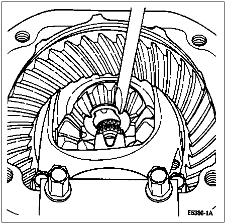
    Install the snap ring in the groove in the shaft. Force the snap ring into position with a screwdriver as shown. Remove the carrier from the holding fixture.


  1. Clean all traces of gasket RTV sealant from the surfaces of the carrier and support arm and make sure the surfaces are free from dirt and oil.

  1. NOTE: The bead should be continuous and should not pass through or outside the holes.

    NOTE: The carrier must be installed on the support arm within five minutes after applying the RTV sealant.

    Apply a bead of Silicone Rubber D6AZ-19562-AA (clear) or -BA (black) or equivalent meeting Ford specifications ESB-M4G92-A and ESE-M4G195-A, in a bead 3-6mm (1/8-1/4-inch) high and wide.

  1. Position the carrier on a suitable jack. Install carrier in position on the support arm using guide pins to align. Install the attaching bolts and hand-tighten. Tighten the bolts in a clockwise or counterclockwise pattern to 41-54 Nm (30-40 lb-ft).

  1. Install support arm tab bolts to side of carrier. Tighten bolts to 115-135 Nm (85-100 lb-ft).

  1. Install both front wheel spindles and the left and right shaft and joint assemblies as described in the Removal and Installation portion of this section.

  1. Connect the driveshaft to the yoke. Install the nuts and U-bolts and tighten to 11-20 Nm (8-15 lb-ft).

  1. Fill with specified lubricant. Refer to Specifications.